Manufacture Routings
Manufacture Routings can be found by navigating to the  tab and clicking on the
 ![]() icon.
The Manufacture Routing Lookup screen will be displayed.
icon.
The Manufacture Routing Lookup screen will be displayed.
Users will be able to view all of the available active Manufactured Items (Finished Goods or Component).
Note
Users can also search Items that are no longer active. To do so, simply use the drop-down menu located under Query and select Inactive Manufacture Routings. This option can be useful especially if a user wishes to reactivate an Item. Rather than re-creating the Item and defining the production requirements, users can simply open the inactive Manufacture Routing to reactivate it.
To open a Manufacture Routing, double-click on the appropriate row. The Manufacture Routing screen will be displayed with the details of the Item.
Adding a New Manufacture Routing
There are three ways to add a new Manufacture Routing to the system. The first way is to press the Ctrl + Shift + M keys. The second way is to navigate to File > New > Manufacture Routing.
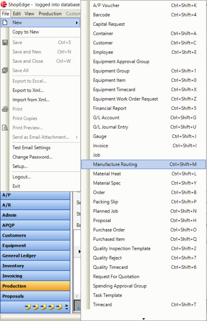
The last way is to click on the  button and select the Manufacture Routing option.
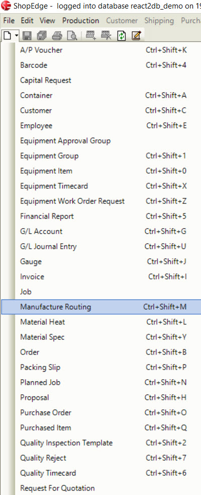
All of these three options will open a new Manufacture Routing screen.
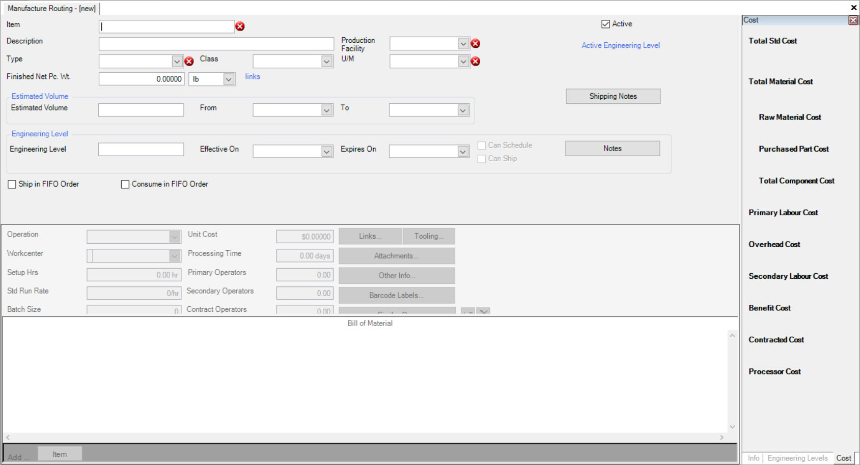
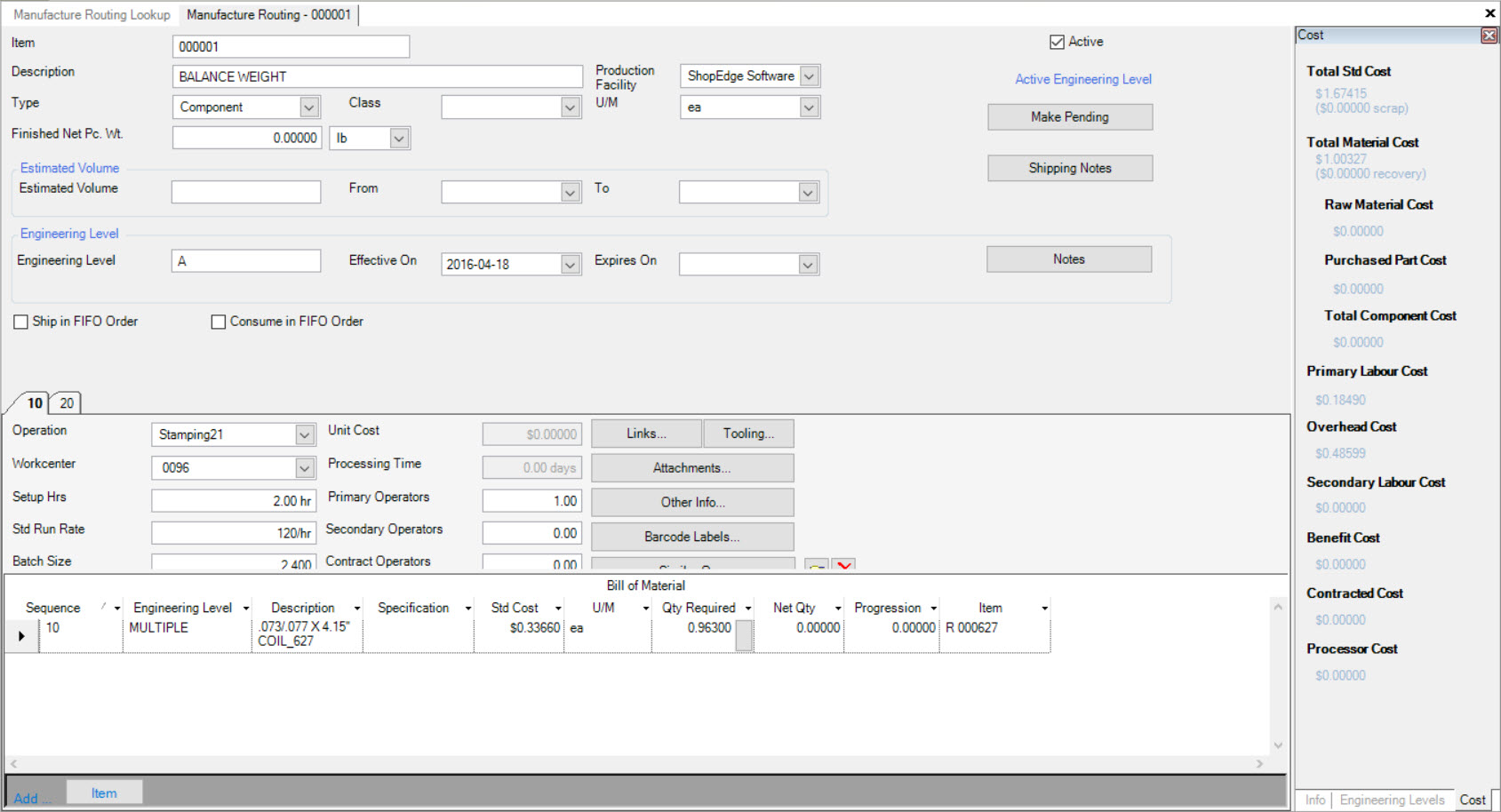
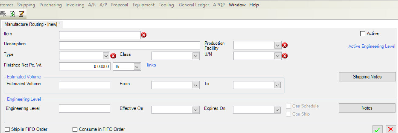
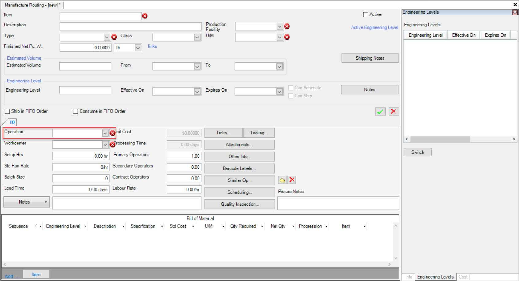
Users must fill in the necessary fields such as the Item, Description, Type, Production Facility, and Unit of Measure (U/M). Other fields such as Class, Finished Net Pc. Wt., Estimated Volume, Shipping Notes, Engineering Level and Notes, and selecting Active, Ship in FIFO Order, and Consume in FIFO Order can be entered in and selected as well.
Adding Operations to a Manufacture Routing
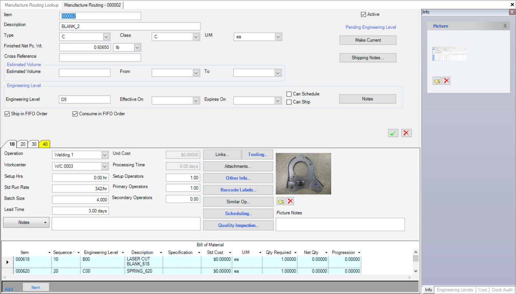
To add an Operation to a Manufacture Routing, click on the  button. A new Operation tab will appear defined with the number 10.
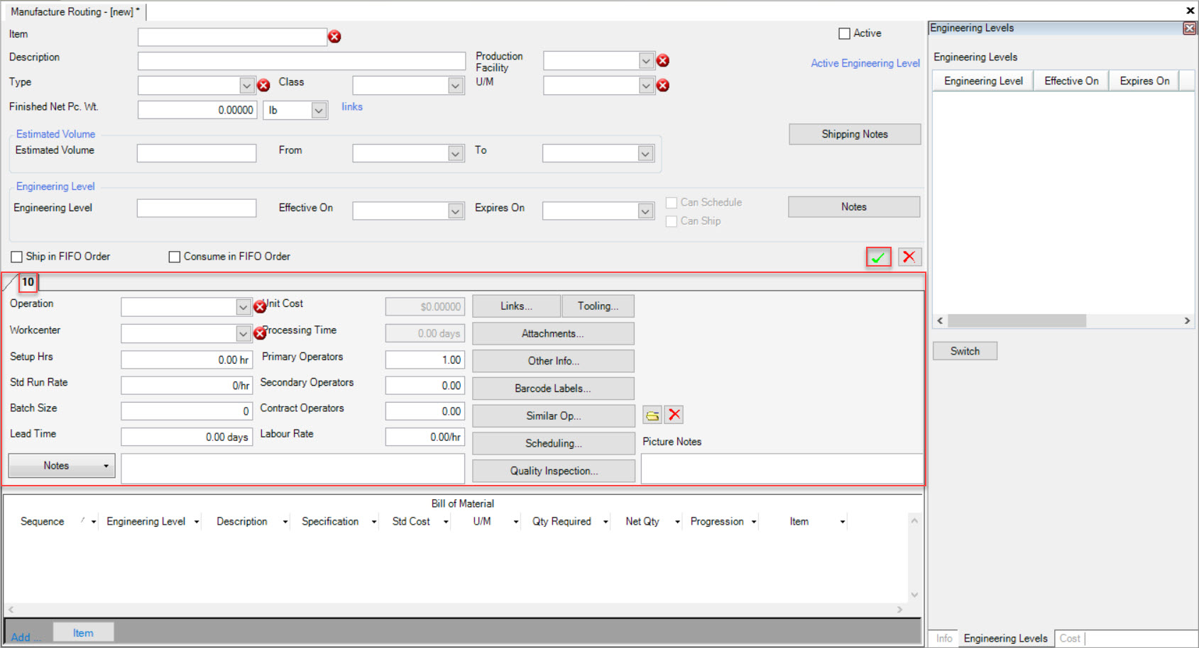
In order to determine how the Item is going to be produced within an Operation, users must consider the following questions:
- What Operations need to be performed to create this Item?
- How many Operations need to be performed to create this Item?
- Are the Operations going to be performed In-House or as Outside Processes?
- How much of the Item is going to be produced (Batch Size)?
Once these questions are considered, users must select the Operation Type (Press, Weld, Sort, Cleansing etc.) using the available drop-down menu.
Note
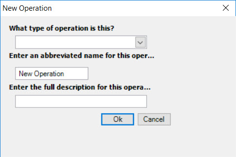
If users wish to manually enter an Operation that is not in the system, simply enter it into the Operation textbox. The system will recognize that it is a new Operation and the New Operation window will appear.
Select the type of Operation and enter in the Abbreviated Name and Description. Click on the  button. The system will add the new Operation Type.
Selecting an Operation as an Outside Process
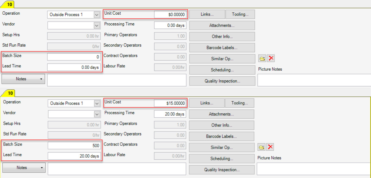
An Outside Process Operation Type will make the Operation tab to be highlighted in yellow.

For an Outside Process, users must select the Operation Type and Vendor using the drop-down menus. The Batch Size, Lead Time, and Unit Cost will default to 0 but should be changed according to the correct values if available.
Note
There is a difference between Lead Time and Processing Time. Lead Time the amount of days before the Item is needed should processing begin. Processing Time is the amount of time it should take the overall process which is calculated internally and not set by the user.
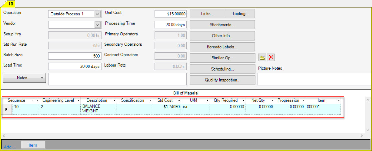
The Bill of Material is not usually necessary to complete for an Outside Process unless some material is being sent to the Vendor to be used during the Outside Process. If this is the case, complete this section by adding an Item.
Click on the  button located at the bottom of the screen. The Item Lookup window will appear where users can located and select an Item(s) to add
to the Bill of Material. Click on the
  button. The Item will be added to the Bill of Material for the Outside Process.
Selecting a Workcenter for an Operation
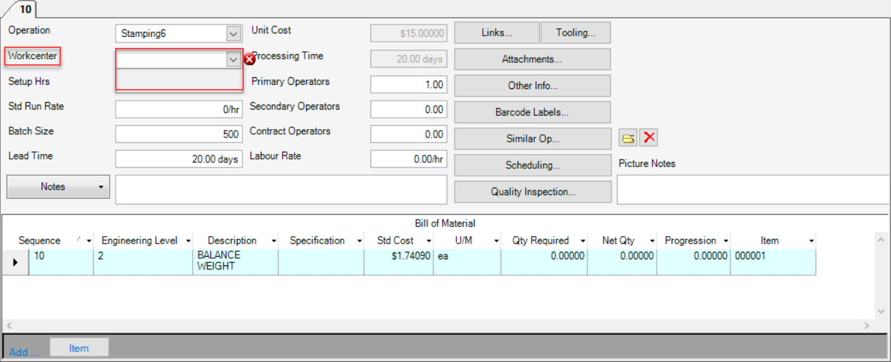
When adding an Operation to a Manufacture Routing, the Workcenter is a necessary field to be completed.
To add a Workcenter, select one using the drop-down menu or manually type it in the textbox.
Note
The Operation can be performed at other Workcenters and move around in the schedule, but the default Workcenter will always be scheduled in the system.
Setup Hours
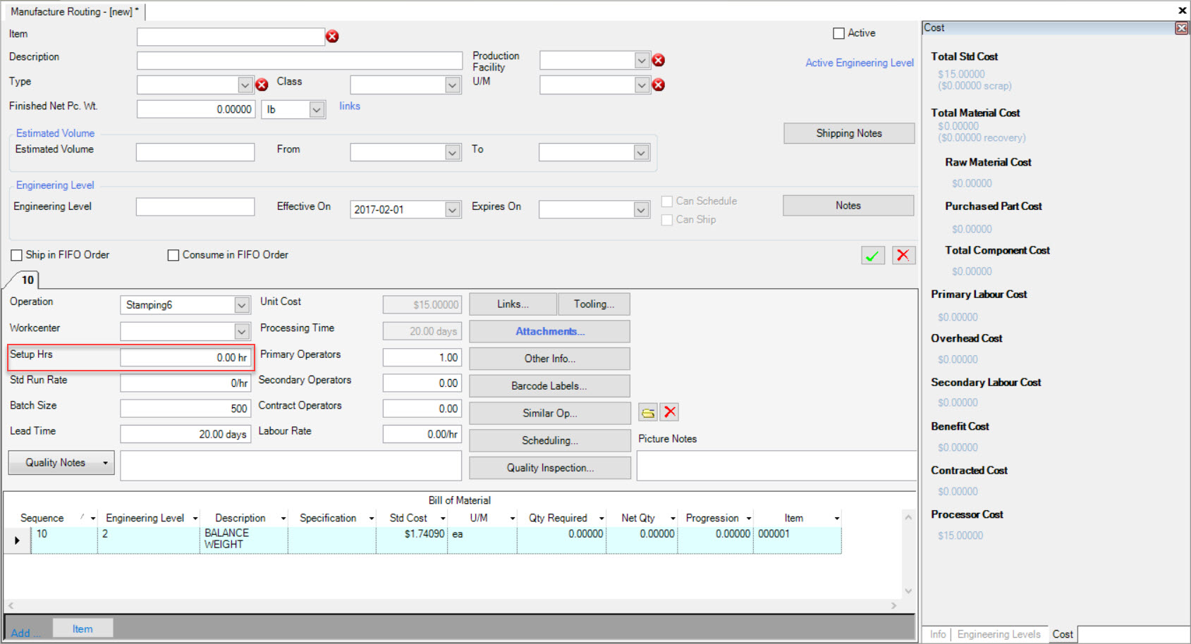
Setup Hours are important for each Operation, and are included in the run-time of every Scheduled Job.
To add Setup Hours, simply enter them into the available textbox located beside Setup Hours on the Manufacture Routing screen.
Standard Run Rate
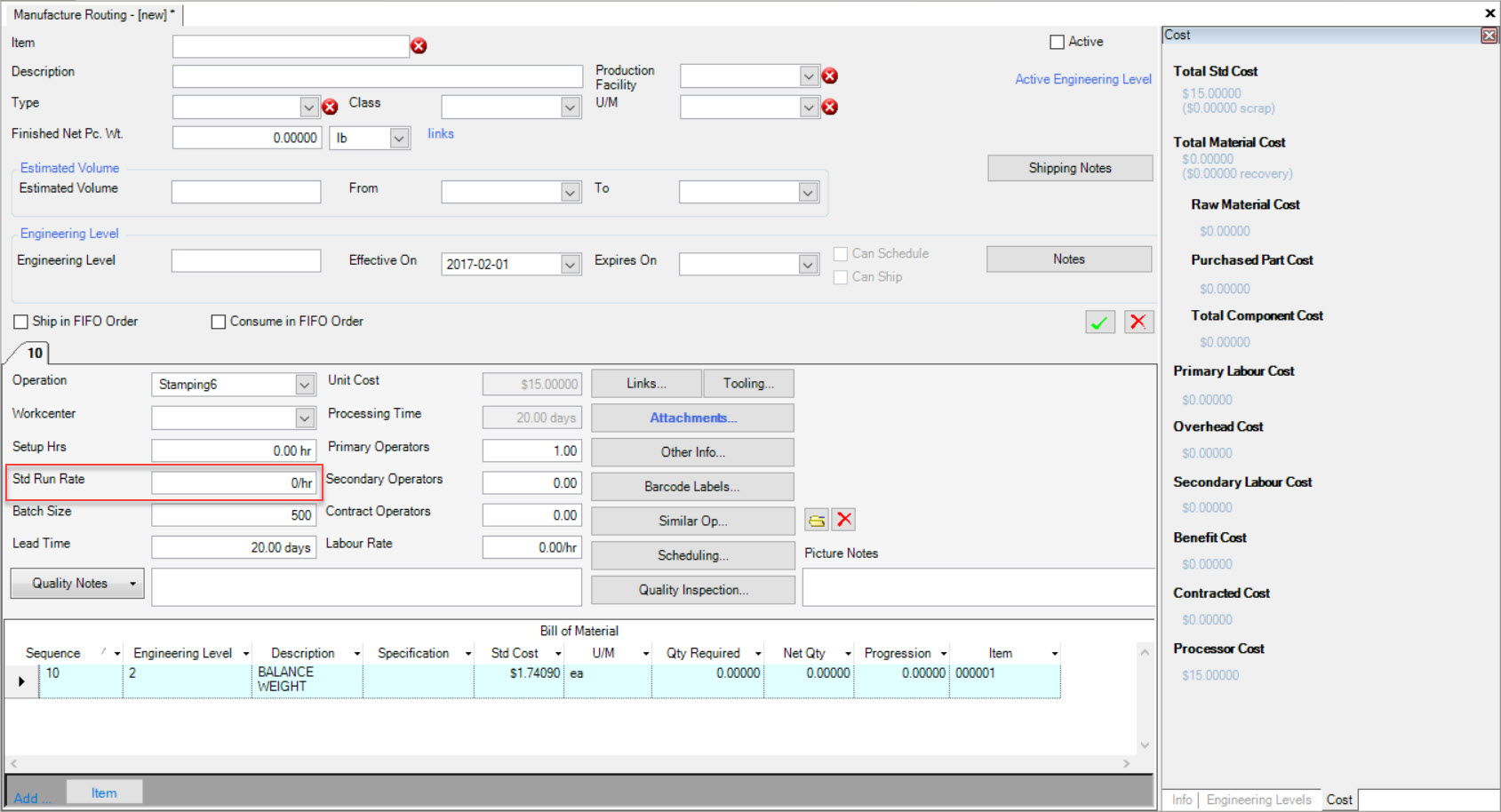
Standard Run Rate is set in the system on the Manufacture Routing, usually based on historical information. It is used throughout the system to calculate Efficiencies such as at the Timecard Level, and in various Reports.
The Standard Run Rate is also used when Scheduling to determine how long a Job is going to run for.
To add the Standard Run Rate, simply type in the rate in the available textbox located beside the Standard Run Rate on the Manufacture Routing screen.
Batch Size
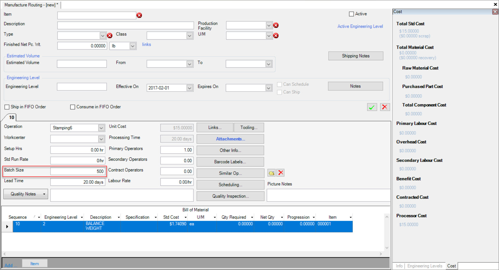
The Batch Size definition in the system is a default Quantity of an Item that is automatically scheduled in the system when a Release is entered into the system for that Item.
If you would like to schedule to the Release Quantity, simply enter the Batch Size as zero in the available textbox. Otherwise, enter the appropriate Batch Size.
Lead Time
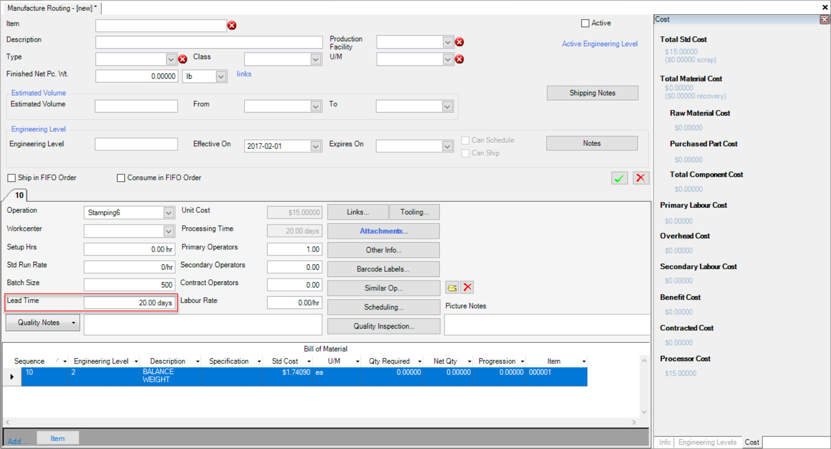
To add Lead Time, simple enter in the number of days in the available textbox for Lead Time on the Manufacture Routing screen.
Setup, Primary, and Secondary Operators
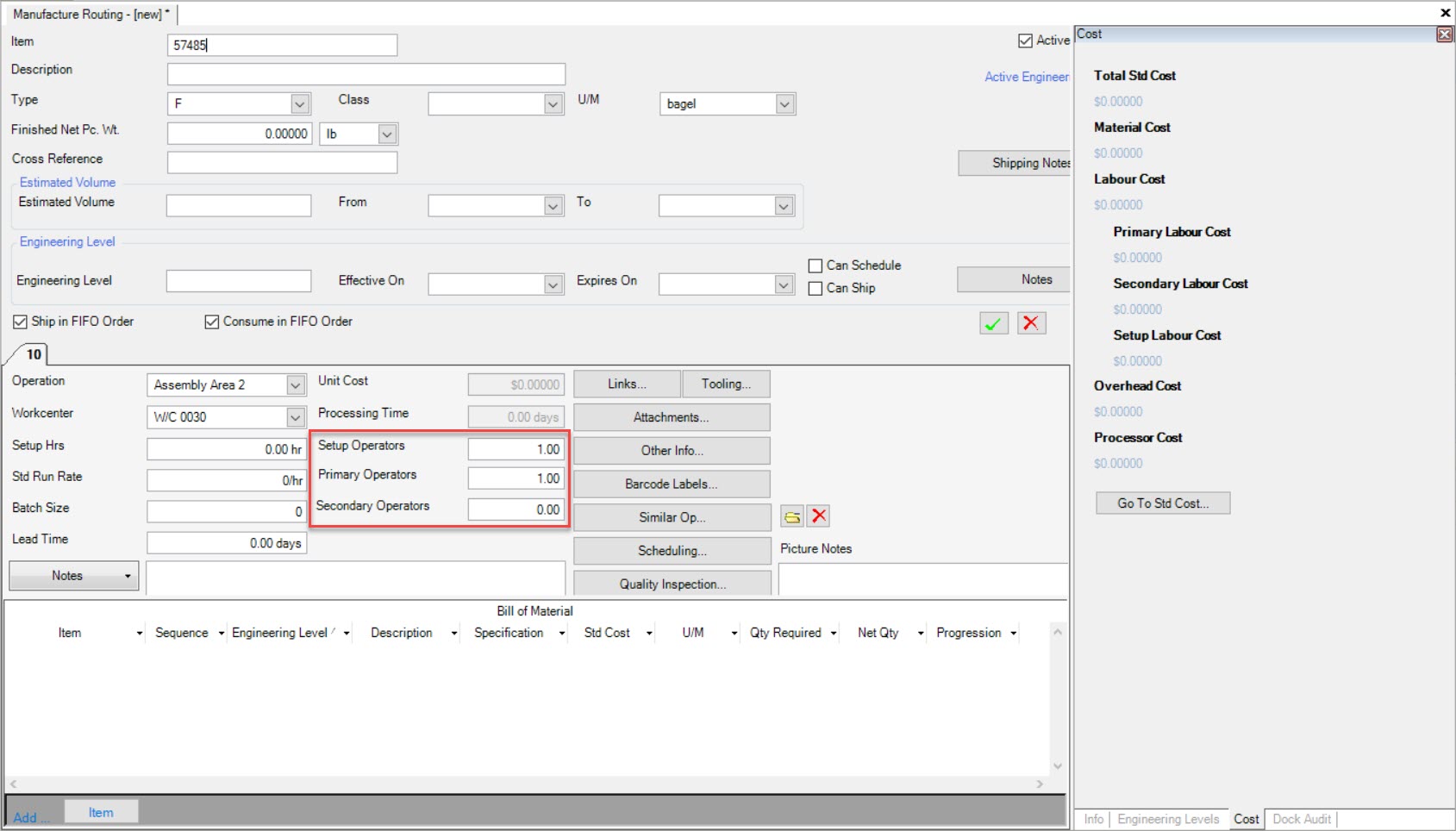
The Setup and Primary Operator textboxes will automatically default to 1. If users wish to have more than 1 Operator for each, users can change the number accordingly. If users wish to have Secondary Operator(s) at the same Workcenter, users can change the numbers accordingly.
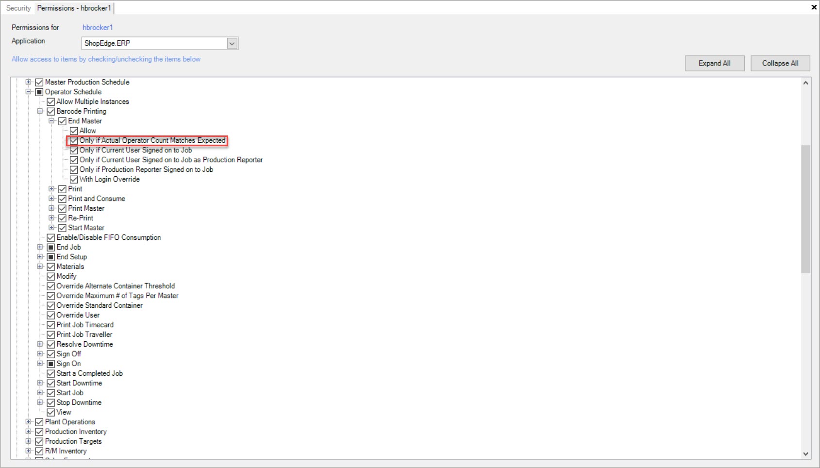
Permissions can also be set in the system under Admin > Security for Operators that will either further or limit actions when on the Operator Schedule screen.
For example, one of the permissions called Only if Actual Operator Count Matched Expected can be found on the Admin > Security > Permissions screen under Production > Operator Schedule > Barcode Printing, Materials, Resolve Downtime, Start Downtime, and Stop Downtime.
If this permission is selected, there must be the expected count of Setup, Primary, and/or Secondary Operators signed onto a Job in order to complete a particular function.
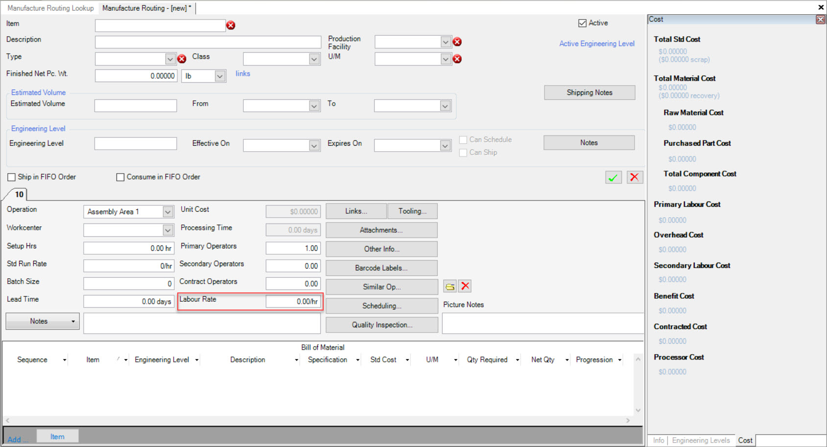
Labour Rate
The Labour Rate is the rate applied to the Contract Operators (if available) when calculating the Operation Total Standard Cost.
Simply enter in the rate per hour in the Labour Rate textbox.
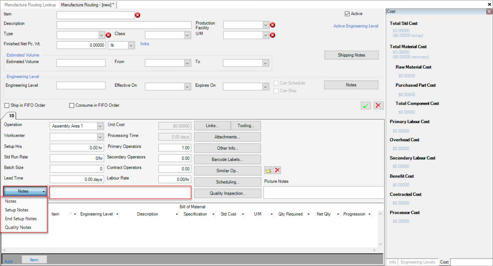
Adding Notes to an Operation
Notes for an Operation can be made visible to the Operators working in Production. Different types of Notes can be selected such as regular Notes, Setup Notes, End Setup Notes, and Quality Notes.
Select the type of Notes you wish to add using the drop-down arrow and type the necessary Notes in the available textbox.
Deleting Notes from an Operation
To delete Notes from an Operation, simply click in the available textbox and use the Backspace key to delete the appropriate Notes. Once Notes have been deleted, Operators will no longer be able to view them.
Make sure to save your changes before exiting the screen.
Adding Links
Users have the ability to link Items for an Operation. This is usually done when two parts are being produced with one tool but have different part numbers. By linking the Items, the system will automatically schedule both part numbers one after the other so they can be produced consecutively.
To link Items, click on the  button. The Linked Operations window will be displayed.
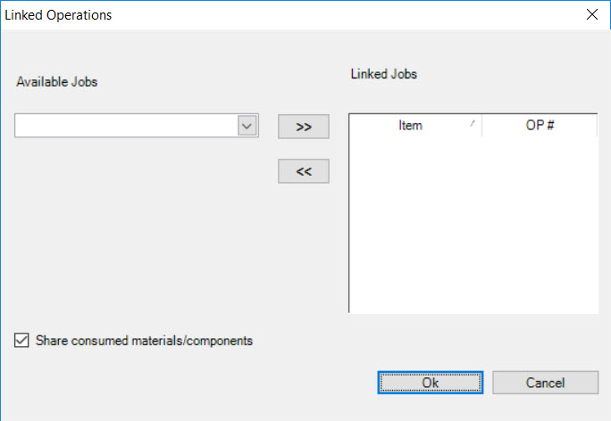
Using the available drop-down menu, select the available Job (Item) you wish to link to the Operation. Then, click on the  button to move the Item
to the Linked Jobs box.
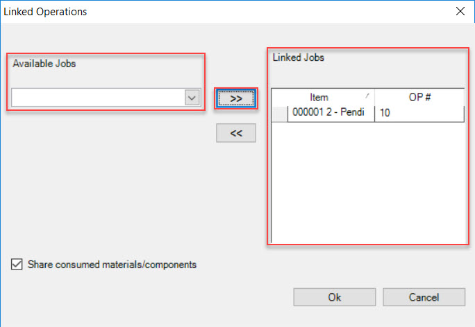
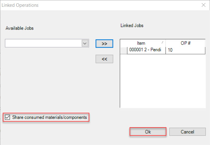
Once you have linked all of the Items you wish to, click on the  button.
Note
If you would like the Linked Items to share the same Raw Material and Components on the Bill of Material, make sure to check the box on the Linked Operations window before clicking on the  button.
Removing Links
To remove a Linked Item on an Operation, click on the  button. The Linked Operations window will be displayed.

Highlight the Linked Item that you wish to remove and click on the  button.
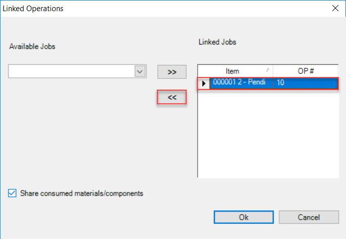
The highlighted Linked Item will be removed from the Operation. Click on the  button to close the Linked Operations window.
Make sure to save your changes before exiting the screen.
Adding Tooling Items
To add a Tooling Item to an Operation, click on the  button. The Tooling Items window will appear.
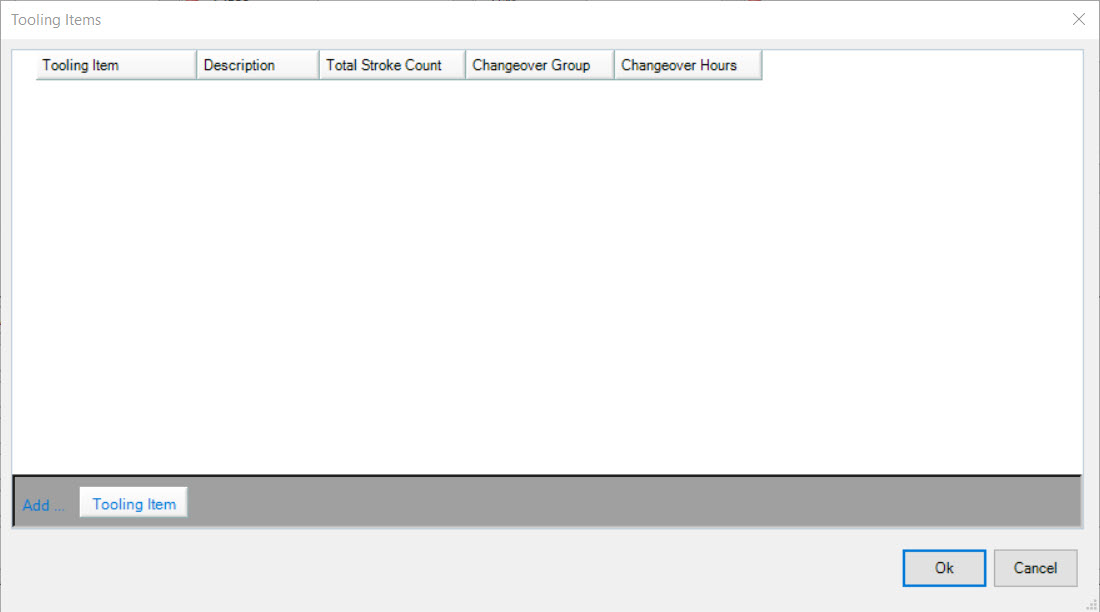
Click on the  button. The Find Tooling Item window will appear.
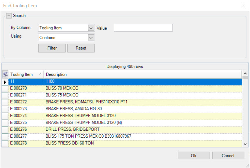
Select the appropriate Tooling Item(s) from the available list and click on the  button. The Tooling Item(s) will appear on the Tooling Items window.
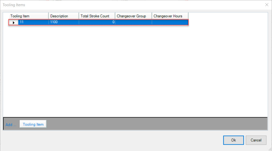
Once you have added the appropriate Tooling Items, click on the  button on the Tooling Items window.
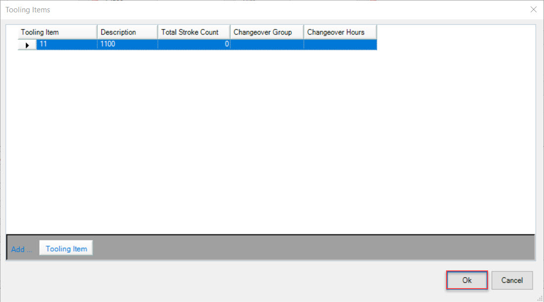
Make sure to save your changes before exiting the screen.
Deleting a Tooling Item
To delete a Tooling Item from an Operation, click on the  button. The Tooling Items window will appear.

Highlight the Tooling Item that you wish to delete. Use your Delete key and when the system prompts you, select Yes.
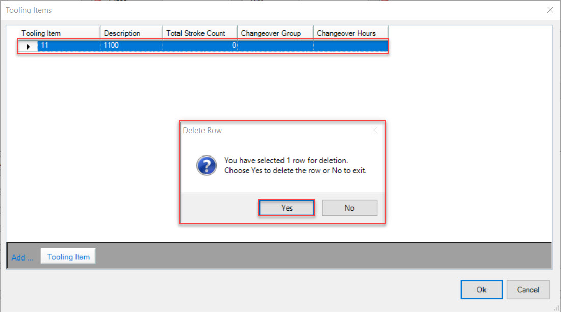
Once the Tooling Item has been deleted, click on the  button to close the Tooling Items window.
Adding Attachments
Users have the ability to add Attachments to an Operation for the use of Operators. Attachments could include Operation Instructions to avoid the use of multiple manual binders at a workstation.
To add an Attachment, click on the  button. The Attachments window will appear.
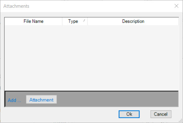
Click on the  button. The system will then allow users to select an Attachment as a file from their computer. Once the Attachment is selected,
click on the
  button.
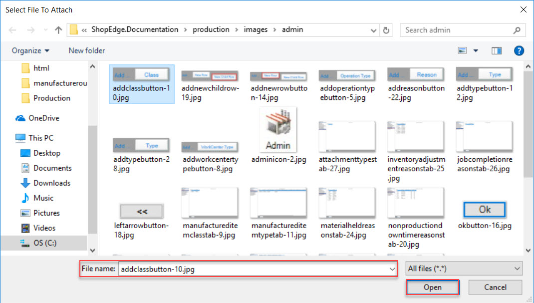
The Attachment will now appear on the Attachments window. Click on the  button to close the window.
Make sure to save your changes before exiting the screen.
Deleting an Attachment
To delete an Attachment from an Operation, click on the  button. The Attachments window will appear.

Highlight the appropriate Attachment that you wish to delete. Use your Delete key and the highlighted Attachment will be removed.
Click on the  button to close the Attachments window.
Make sure to save your changes before exiting the screen.
Other Info
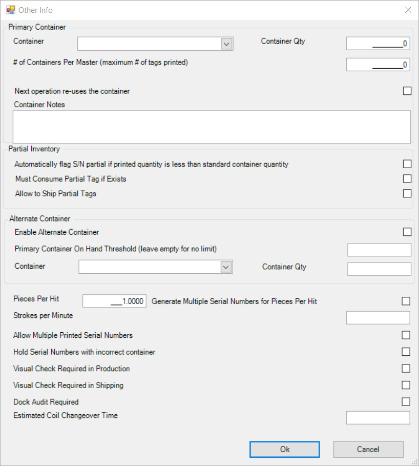
Other Info includes details regarding Containers, Pieces Per Hit, Strokes Per Minute, Master Container Information, and Container Notes.
To open the Other Info screen, click on the  button. The Other Info window will be displayed.
Primary Container
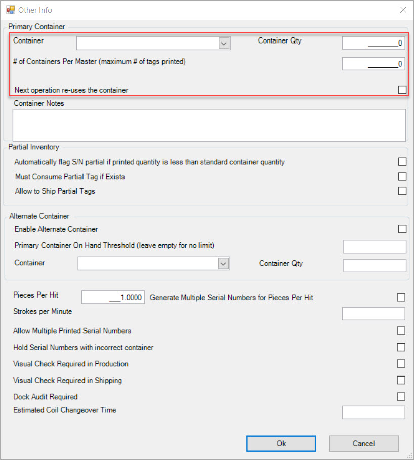
The Primary Container section is the first section on the Other Info window. This section allows users to select a Primary Container used for an Item at an Operation.
Users can select the Container using the available drop-down menu and enter in the Container Qty, and the # of Containers Per Master (if necessary).
Users can also select whether or not they would like the next Operation to re-use the selected Container.
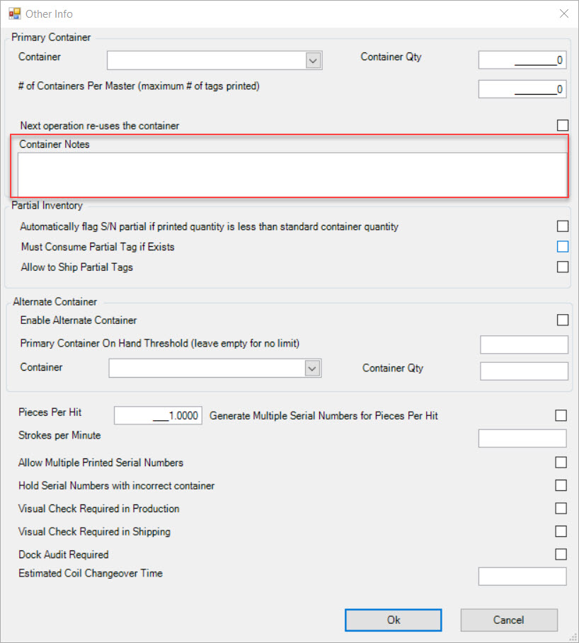
If users have Notes that they would like to add regarding the selected Primary Container, simply enter them in the textbox provided.
Partial Inventory
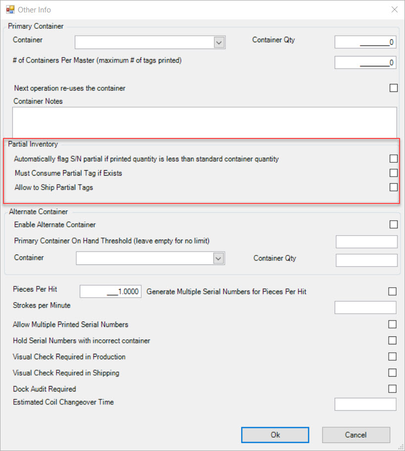
The Partial Inventory section is the second section on the Other Info window. These flags allow users to set up Tags to have a Partial Inventory.
Users can select or de-select the following boxes:
- Automatically flag S/N (Serial Number) Partial if printed Quantity is less than Standard Container Quantity
- Must Consumer Partial Tag if Exists
- Allow to Ship Partial Tags
Alternate Container
The Alternate Container section is the third section on the Other Info window. This section allows users to have an Alternate Container aside from the Primary Container.
To enable the Alternate Container, users must select the Enable Alternate Container box.
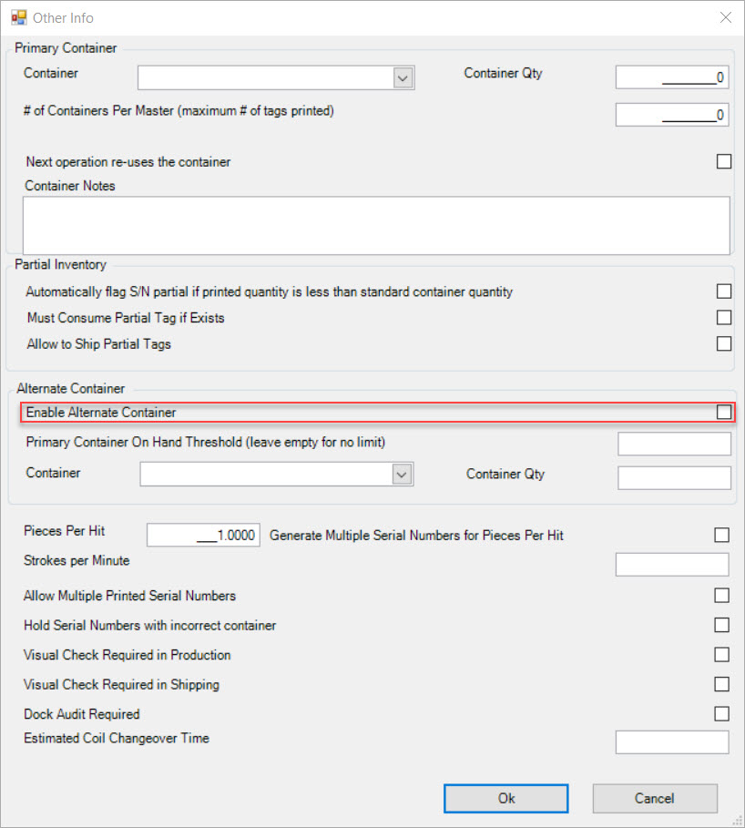
Enter in an amount for the Primary Container On-Hand Threshold (leave empty for no limit) if necessary. Then select an Alternate Container using the drop-down menu and enter in the Container Qty.
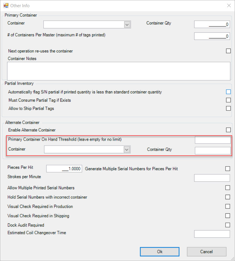
Additional Info on the Other Info Window
The last section of the Other Info window contains additional settings regarding Containers for the Operation.
- Pieces Per Hit: allows users to indicate how many pieces are produced at a particular Operation. For example, if the Tooling Item produces two pieces with the same Item #, the number of Pieces Per Hit would be 2.
- Generate Multiple Serial Numbers for Pieces Per Hit: users can select this checkbox if they are creating more than one Piece Per Hit and each piece requires it’s own Serial Number.
- Strokes Per Minute: allows users to enter in the actual Machine Rate which is used in OEE calculations.
- Allow Multiple Printed Serial Numbers: selecting this checkbox would allow Operators to print more than one Serial Number at a time.
- Hold Serial Numbers with incorrect container: selecting this checkbox will set whether Serial Numbers will be held if they are assigned to an incorrect Container.
- Visual Check Required in Production: selecting this checkbox sets whether or not a Visual Check is required in Production.
- Visual Check Required in Shipping: selecting this checkbox sets whether or not a Visual Check is required in Shipping.
- Dock Audit Required: this checkbox enables or disables whether a Dock Audit is required. The Dock Audit is an inspection that has to be carried out before the product is allowed to leave the Workcenter. When a user decides to set an Item to require a Dock Audit, the only thing the Item cannot do, is leave the Workcenter.
Note
If the Dock Audit Required checkbox is enabled on a Manufacture Routing, only new Items will be affected. If the chexbox is ever disabled, any previous Items that required a Dock Audit will still go through the process. Disabling Dock Audits will only affect newly added Items to the Manufacture Routing.
Note
If a Dock Audit is selected for an Item, the user will then be able to navigate to the Operator Schedule screen and view that the Status was changed to Audit under the Production Tab.
Note
For more information on how to perform a Dock Audit, please see Quality Assurance > Dock Audits.
- Estimated Coil Changeover Time: allows users to set an Estimated Coil Changeover Time on a particular Operation.
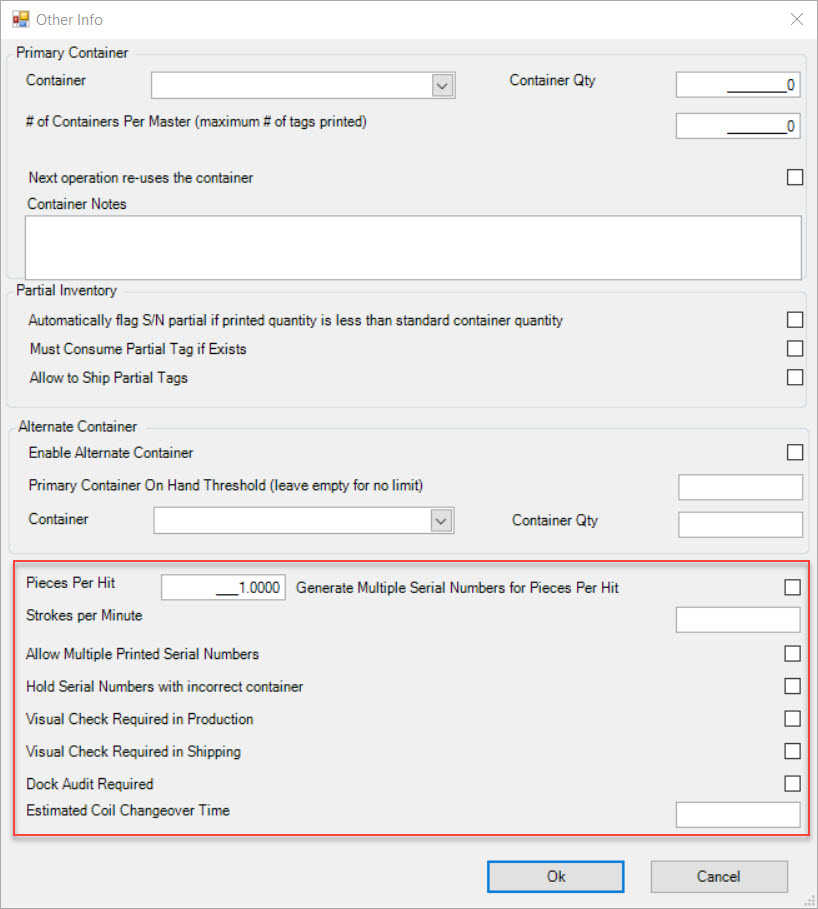
Once all of the necessary fields are completed, click on the  button to close the Other Info window.
Make sure to save your changes before exiting the screen.
Releasing a Dock Audit
If users select the checkbox on the Other Info window to enable a Dock Audit for an Operation, they will have to release it as well.
To release a Dock Audit, users must navigate to the  tab and click on the
 ![]() icon. The
Dock Audit Lookup screen will be displayed.
icon. The
Dock Audit Lookup screen will be displayed.
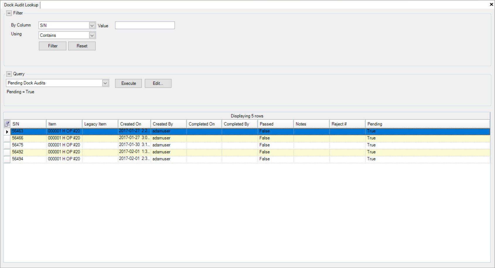
Select an Item and double-click on the appropriate row to open the Manufactured Item Tag screen.
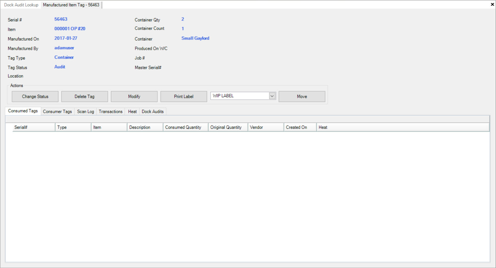
Click on the  button. The Change Status window will appear.
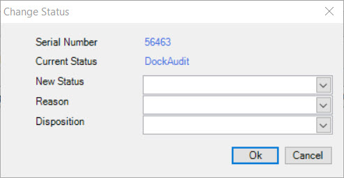
Using the drop-down menus, select a New Status, Reason, and Disposition. Click on the  button.
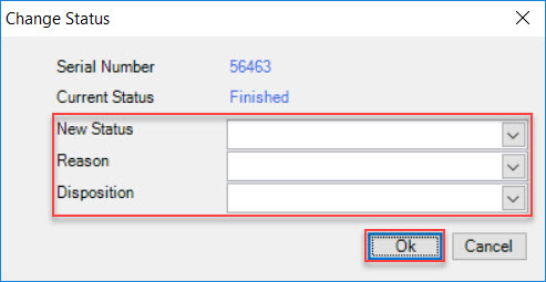
The Status will then be updated on the Manufactured Item Tag screen and will reflect the changes made by the user.
Barcode Labels
Barcode Labels are created and maintained in the system under Admin > Barcodes. Users are then able to attach Barcodes to the Item of the Operation in the Manufacture Routing.
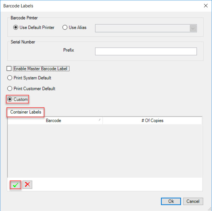
To do so, click on the  button. The Barcode Labels window will appear.
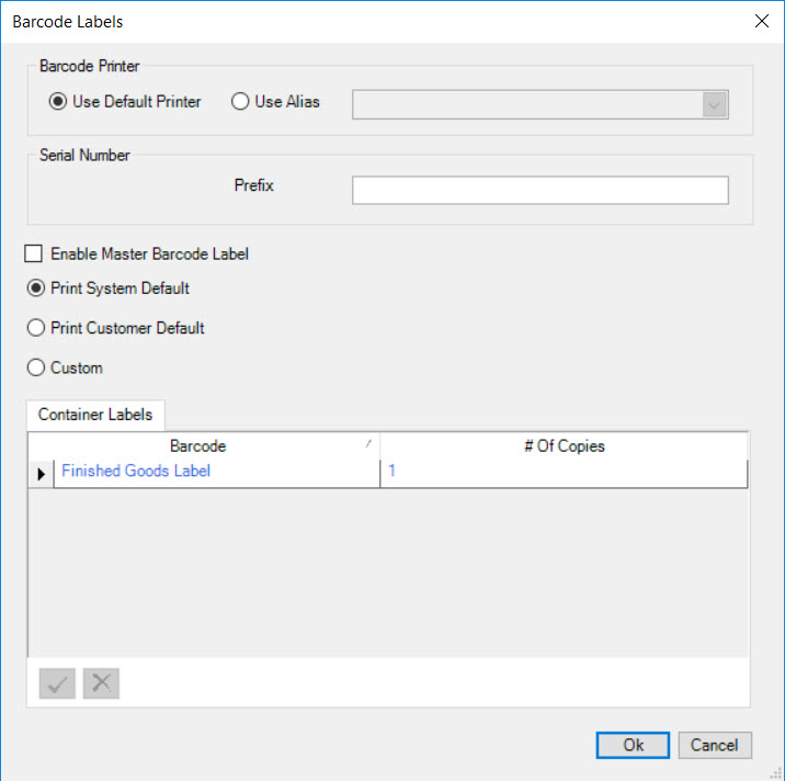
Users must select the Barcode Printer either using the Default Printer or the Alias. If selecting the Alias Printer, users must select the position using the drop-down menu. A Prefix for the Serial Number must be entered as well.
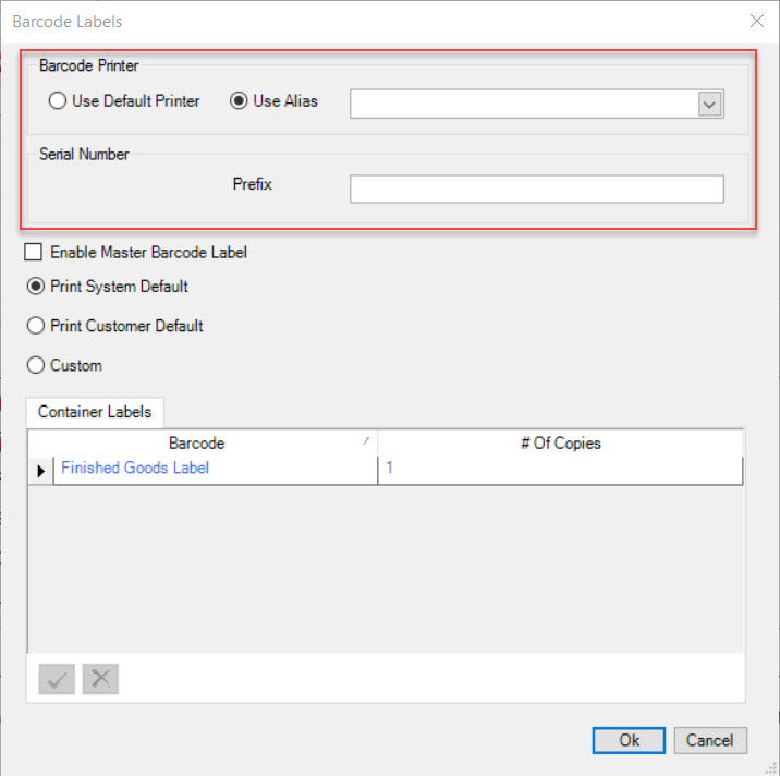
Next, users are given options to:
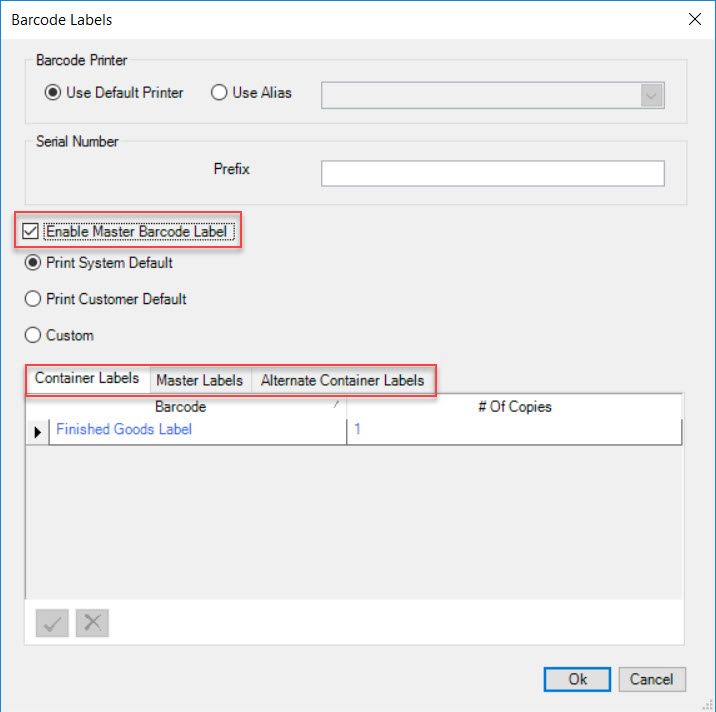
- Enable Master Barcode Label: by checking this box, two new tabs will appear beside the Container tab; Master Labels and Alternate Container Labels. The system will automatically select a Barcode for each tab. Selecting this option will apply the System Default Barcode Label and a Customer Default Barcode Label to the Master Label.
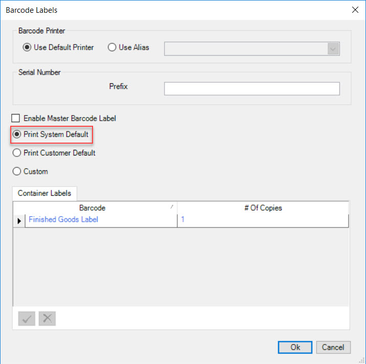
- Print System Default: selecting this option will apply the System Default Barcode Label to an Item’s Operation. These Labels are originally created in the Admin module.
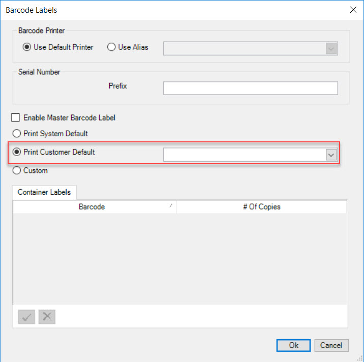
- Print Customer Default: selecting this option will apply a Customer Default Barcode Label to an Item’s Operation. Make sure to select the Customer using the available drop-down menu.
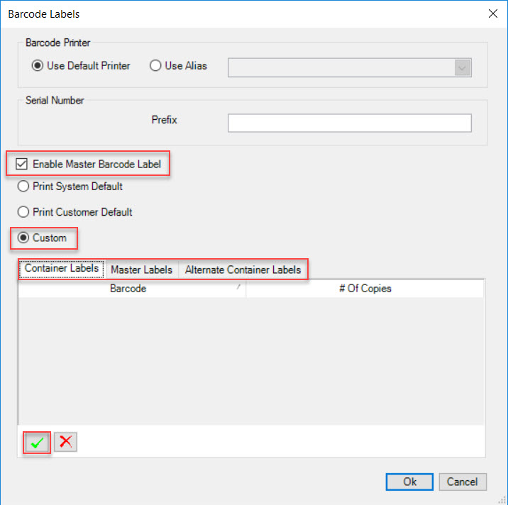
- Custom: selecting this option allows users to add a custom Label from the available tabs: Container Labels, Master Labels, and/or Alternate Container Labels. Clicking on the
 button on each tab will display a new row. Users must select the Barcode and enter in the # of Copies.
Note
If users select this option without enabling the Master Barcode Label, they will only be able to add a Barcode to the Container Labels tab.
Note
If users wish to delete a custom Label, simply highlight the Barcode row under the appropriate tab and click on the  button. When the system prompts you, select Yes.
Once all necessary fields are complete, click on the  button to close the Barcode Labels window.
Make sure to save your changes before exiting the screen.
Linking a Similar Operation (Op)
Users have the ability to allow two Operations on the schedule to begin at the same time. This can occur if the Operations have different part numbers but use the same Raw Material. One thing that may be different about the parts is the way that they are stacked in the bin (up/down etc.).
To add Similar Operations, click on the  button. The Similar Operations window will appear.
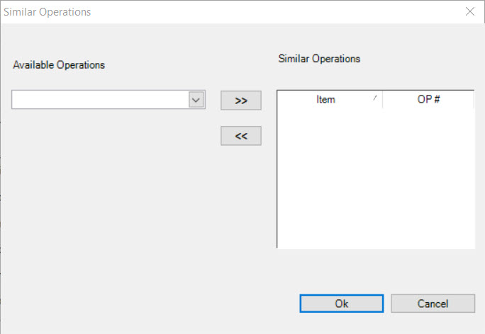
Select similar Jobs from the Available Operations drop-down menu and then click on the  button to add it to the Similar Operations box.
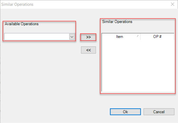
Once the appropriate Similar Operations are added, click on the  to close the Similar Operations window.
Make sure to save your changes before exiting the screen.
Unlinking a Similar Op
To unlink a Similar Operation from an Operation, click on the  button. The Similar Operations window will appear.

Highlight the Similar Operation that you wish to unlink and click on the  button. The highlighted Operation will be unlinked.
When you are finished unlinking a Similar Operation, click on the  button to close the Similar Operations window.
Scheduling
Scheduling allows users to make changes to Scheduling Parameters for an Item at an Operation.
Click on the  button. The Scheduling window will appear.
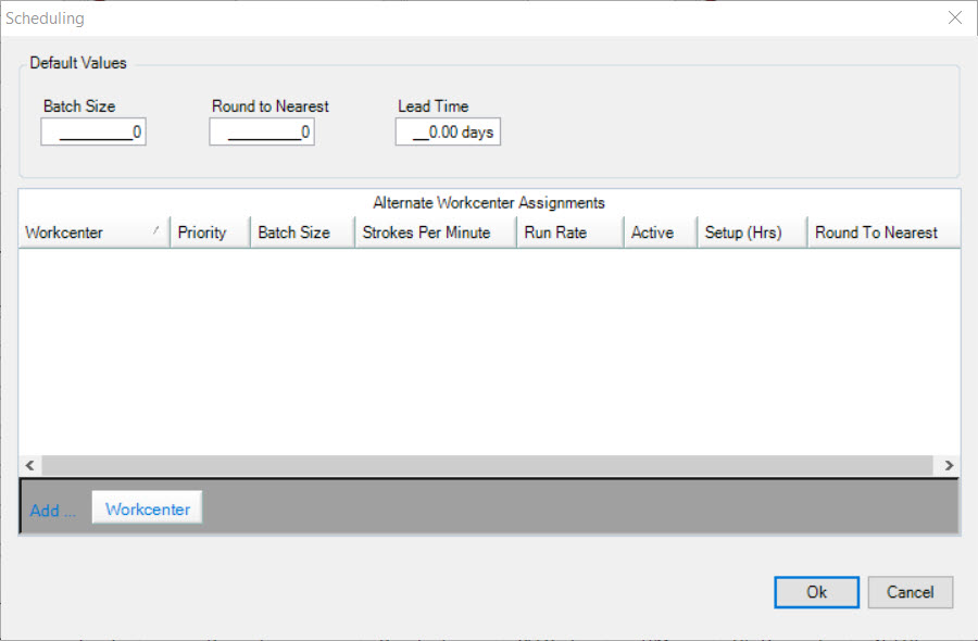
Users can enter in the Default Values such as the Batch Size, Nearest Value to Round to, and the Lead Time.
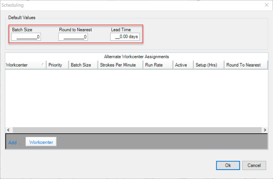
Click on the  button to close the Scheduling window.
Make sure to save your changes before exiting the screen.
Adding a Workcenter
Users may also choose to add a Workcenter in the Scheduling window by clicking on the  button. A new row will appear. Users must select and
enter in the appropriate information into the fields.
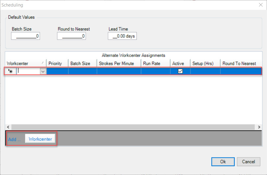
Click on the  button to close the Scheduling window.
Make sure to save your changes before exiting the screen.
Deleting a Workcenter
To delete a Workcenter from the Scheduling window, click on the  button. The Scheduling window will appear.

Highlight the appropriate Workcenter that you wish to delete. Use your Delete key and when the system prompts you, select Yes.
The highlighted Workcenter will be deleted. Click on the  to close the Scheduling window.
Make sure to save your changes before exiting the screen.
Quality Inspection
Quality Inspection can be used if users wish to add an Inspection to an Item at a particular Operation.
To add a Quality Inspection to an Operation for an Item, click on the  button. The Quality Inspection Specifications window will
appear.
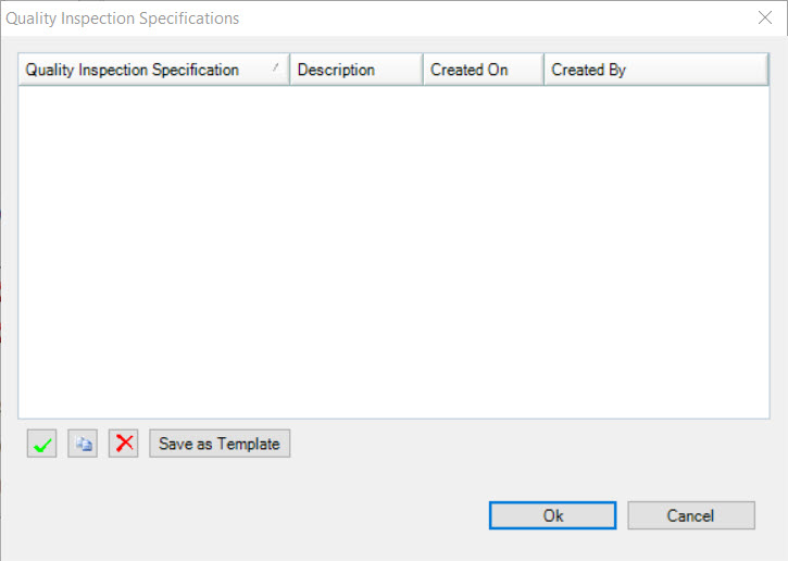
You will notice that there are two ways to add a Quality Inspection template. Users have the option to add a new Quality Inspection template, or add an existing Quality Inspection template.
Adding a New Quality Inspection Template
To add a new Quality Inspection template, click on the  . The Create Quality Inspection Specification for (Operation #) window will appear.
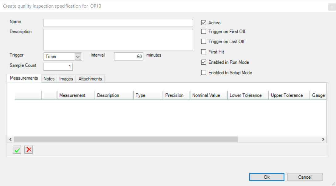
Users must fill in the Quality Inspection Name, Description, select the Trigger (None, or Timer), enter in the Interval Minutes if Timer was selected as the Trigger, and enter in a Sample Count Quantity.
To the left of the window, users have the option to select or de-select the following settings:
- Active
- Trigger on First Off
- Trigger on Last Off
- First Hit
- Enabled in Run Mode
- Enabled in Setup Mode
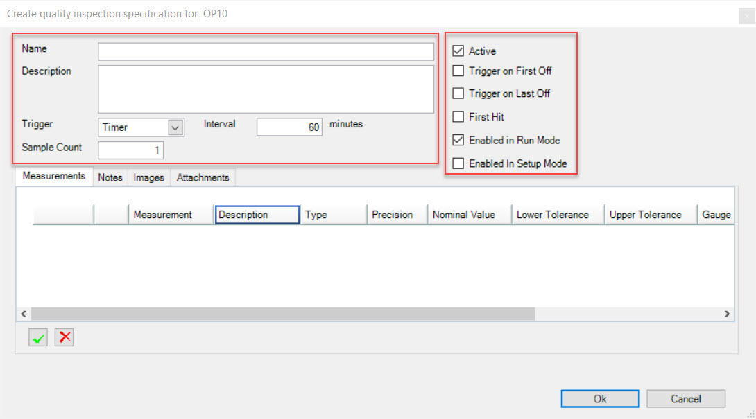
Once the header information is completed for the new Quality Inspection template, users can navigate through the different Tabs and add or remove items such as Measurements, Notes, Images, and/or Attachments.
To add a Measurement, make sure the  tab is selected.
Click on the  button. The Measurement Definition window will appear.
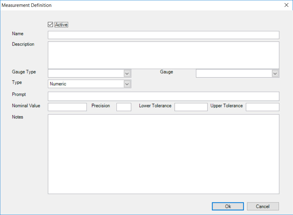
Enter in the Measurement Name, Description, select the Gauge Type (Attribute, Functional, Gauge Rack, Misc., or Variable), Gauge, and Type. Next, enter in the Prompt, Pass Prompt, Fail Prompt, and any
necessary Measurement Notes. Once the necessary fields have been completed, click on the  button.
A new row will appear with the Measurement that was just created. Users now have the option to add an image to the Measurement if necessary by clicking on the  button in the appropriate row.
The system will then allow you to select an image from your computer. Once an image has been selected, click on the  button to attach the image.
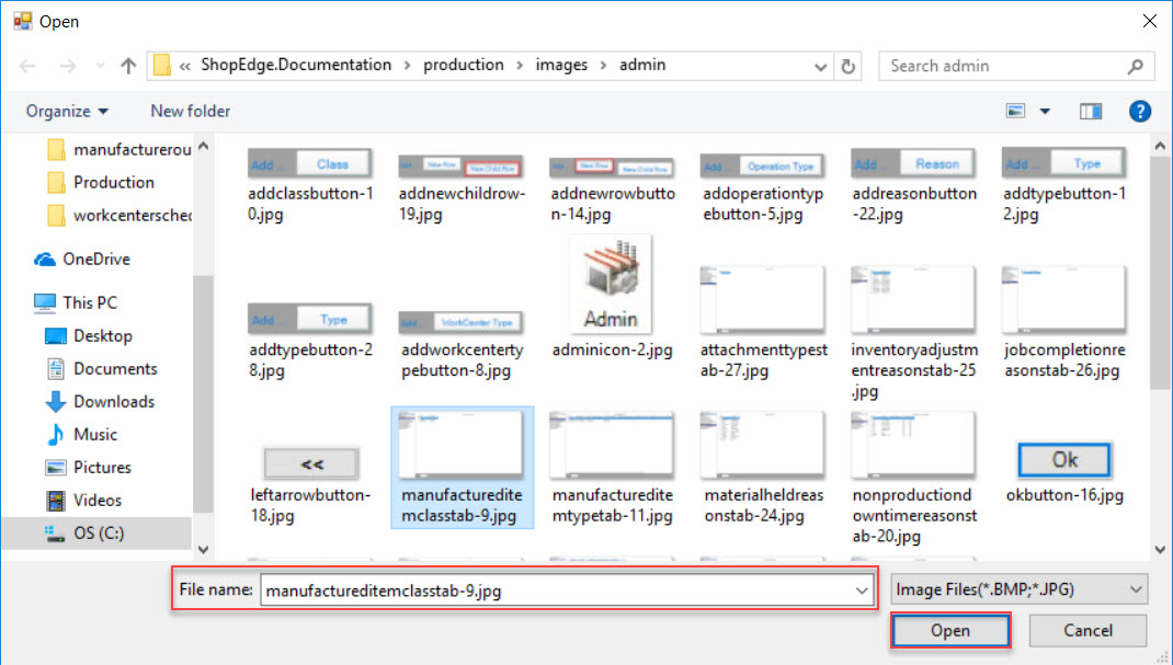
A plus sign will appear beside the Measurement row. To view the attached image, click on the plus sign.
Note
To delete a Measurement image, simply highlight the appropriate row and click on the  button. The highlighted Measurement will be deleted.
To add Notes to a Quality Inspection, make sure that the  tab is selected.
Click on the  button. A Notes window will appear with a textbox. Enter in any necessary Notes and click on the
 button.
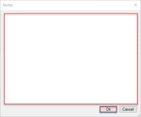
The Notes will be added as a new row. To view the details of the Note, double-click on the appropriate row.
Note
To delete a Quality Inspection Note, simply highlight the appropriate row and click on the  button. The highlighted Note will be deleted.
To add an image to a Quality Inspection, make sure that the  tab is selected.
Click on the  button. The system will allow you to select an image from your computer to add to the Quality Inspection. Once an image is selected,
click on the
  button. The Image will then appear as a new row. To change the image, simply double-click on the appropriate row and select a different image
from your computer.
Note
To delete a Quality Inspection image, simply highlight the appropriate row and click on the  button. The highlight image will be deleted.
To add an Attachment to a Quality Inspection, make sure that the  tab is selected.
Click on the  button. The Browse For Folder window will appear. Users have the option to select an existing Folder or make a New Folder.
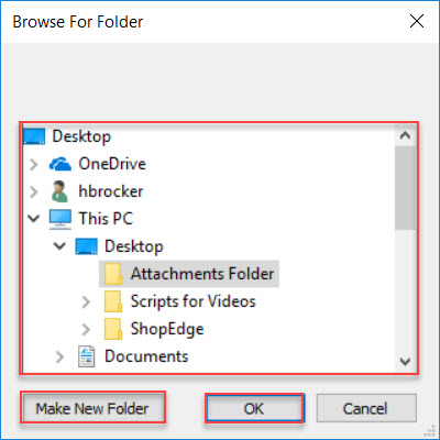
Once a Folder has been selected, click on the  button.
The Folder field will automatically update to the Folder that was selected. If necessary, fill in the remaining fields.
Users also have the option to add Other Attachments by clicking on the  button. The system will allow users to select Other Attachments from their
computer. Once an Attachment is selected, click on the
  button. The selected Attachment will be added to the Other Attachments section under the
 tab.
tab.
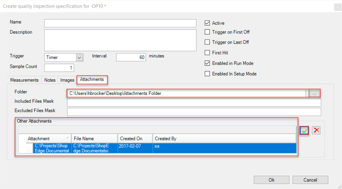
Once all necessary fields have been completed on the new Quality Inspection template, click on the  button. The new Quality Inspection
template will appear as a new row on the Quality Inspection Specifications window.
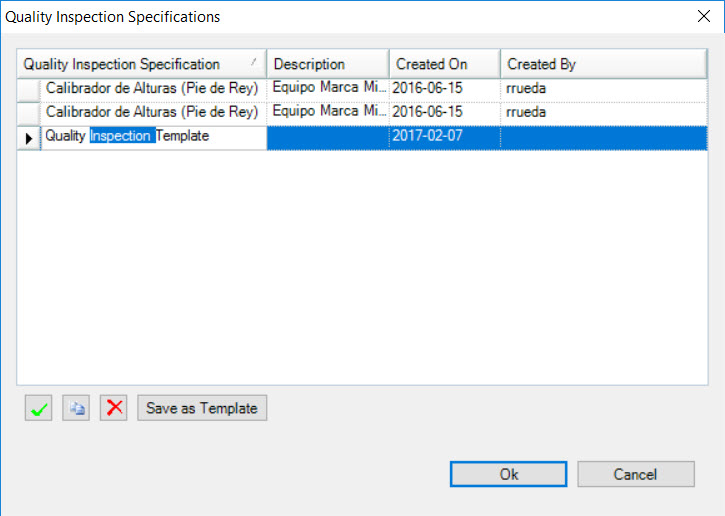
In order to save a new Quality Inspection, users must highlight the appropriate row and click on the  button to save the new Quality Inspection
as a template.
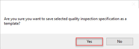
A confirmation window will appear, making sure that users want to save the selected Quality Inspection as a template. Click on the  button to confirm.
Click on the  button to close the Quality Inspection Specifications window.
Make sure to save your changes before exiting the screen.
Adding an Existing Quality Inspection Template
To add an existing Quality Inspection template, click on the  button. The Quality Inspection Specifications window will
appear.

Click on the  button. The Quality Inspection Template Lookup window will appear.
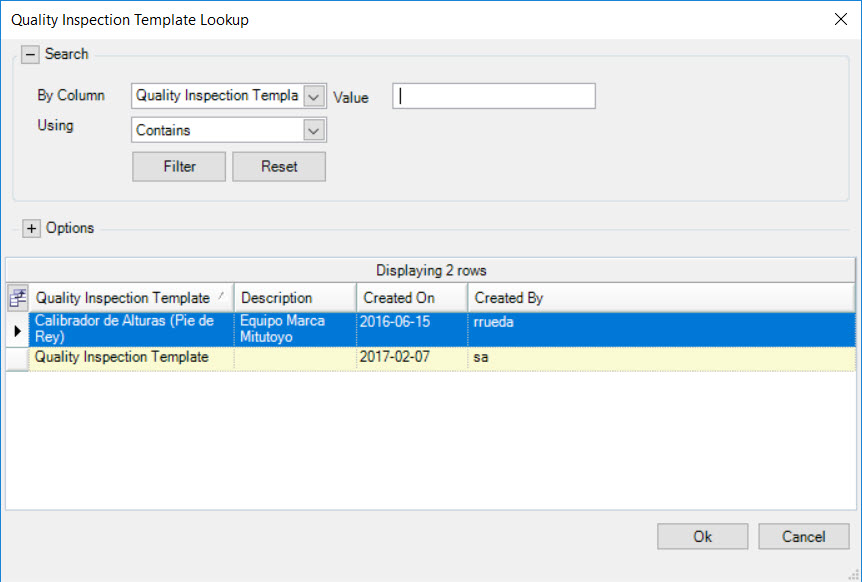
Select the Quality Inspection template and click on the  button. This will open the Copy Quality Inspection Template for (Operation #) window.
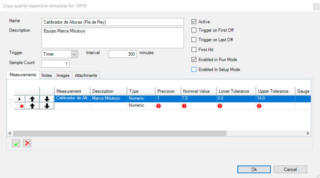
Users can modify any header information as well as the Tabs including Measurements, Notes, Images, and Attachments accordingly.
Note
For more detailed information on how to view, add, edit, or delete information on an existing Quality Inspection template, please see the section on Adding a New Quality Inspection Template.
Once the appropriate modifications are made, click on the  button. The existing Quality Inspection template with the appropriate modifications made to it,
will now be added to the Quality Inspection Specifications window. Highlight the row and click on the
  button.
A confirmation window will appear, making sure that users want to save the selected existing Quality Inspection with modifications as a template. Click on the  button to confirm.

Click on the  button to close the Quality Inspection Specifications window.
Make sure to save your changes before exiting the screen.
Deleting a Quality Inspection Template
To delete a Quality Inspection template, click on the  button.
Highlight the row of the Quality Inspection template that you wish to delete and click on the  button. The highlighted Quality Inspection template will be
deleted.
Click on the  button to close the Quality Inspection Specifications window.
Make sure to save your changes before exiting the screen.
Adding a Picture to an Operation
Users have the ability to add a picture for an Operation. To do so, click on the  button.
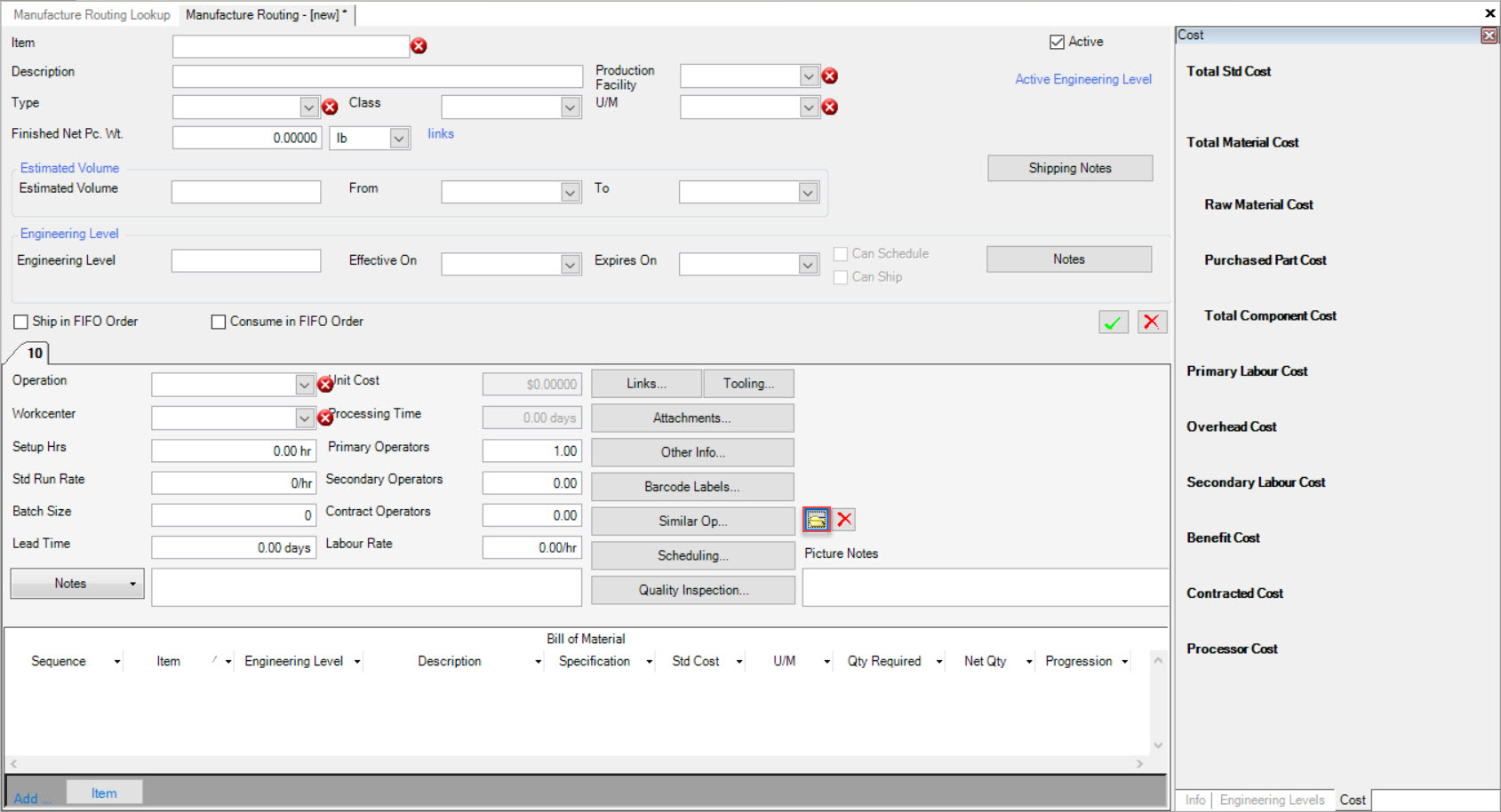
The system will then allow users to select a picture from their computer. Once a picture has been selected, click on the  button.
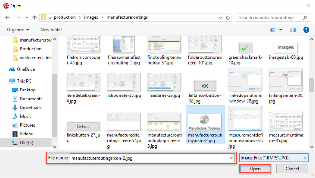
The selected picture for the Operation will now appear on the Manufacture Routing screen, above the  button.
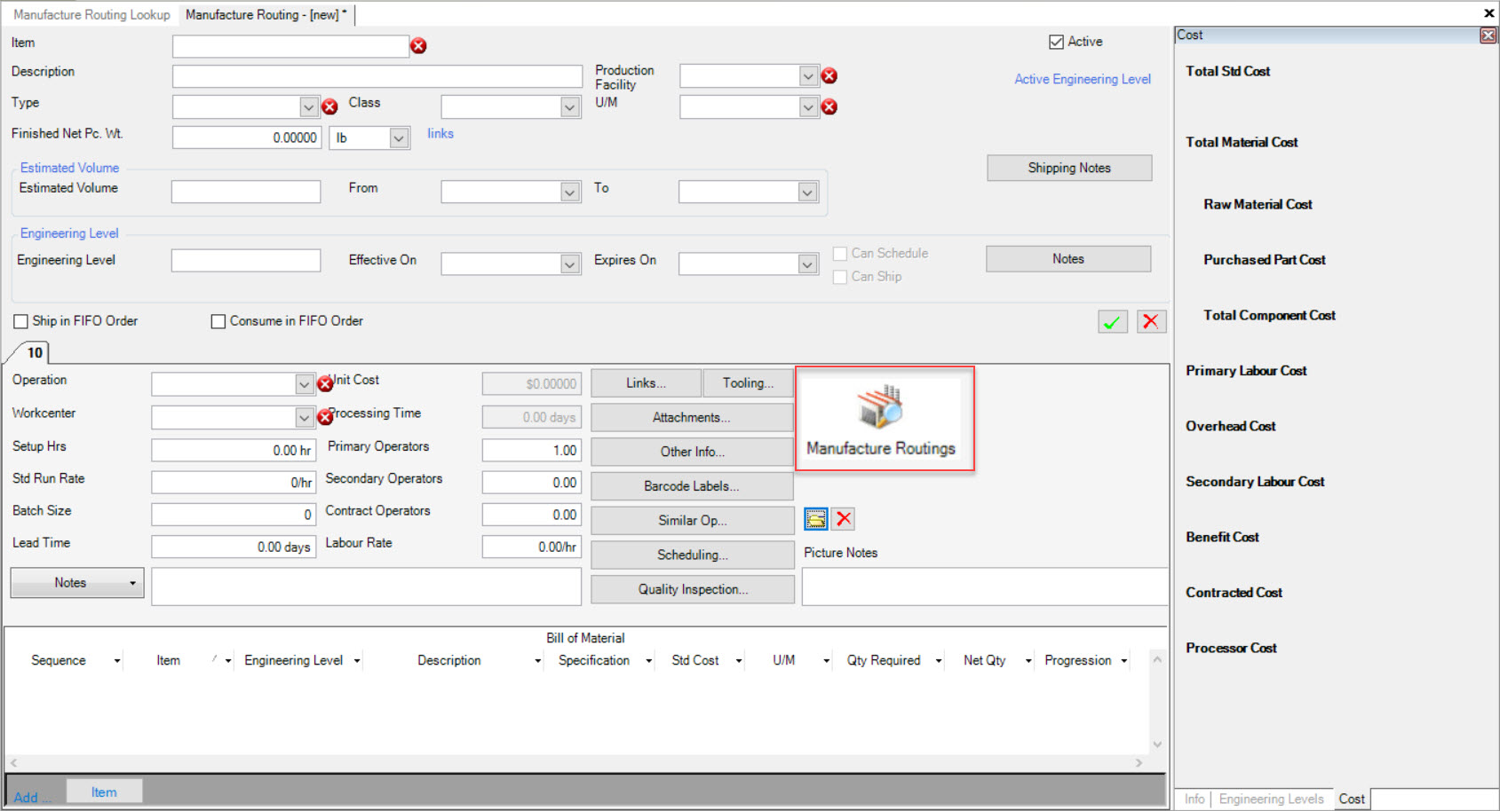
Make sure to save your changes before exiting the screen. The picture will be visible to the Workcenter Operator.
Deleting a Picture from an Operation
To delete a picture from an Operation, simply click on the  button located below the picture on the Manufacture Routing screen.
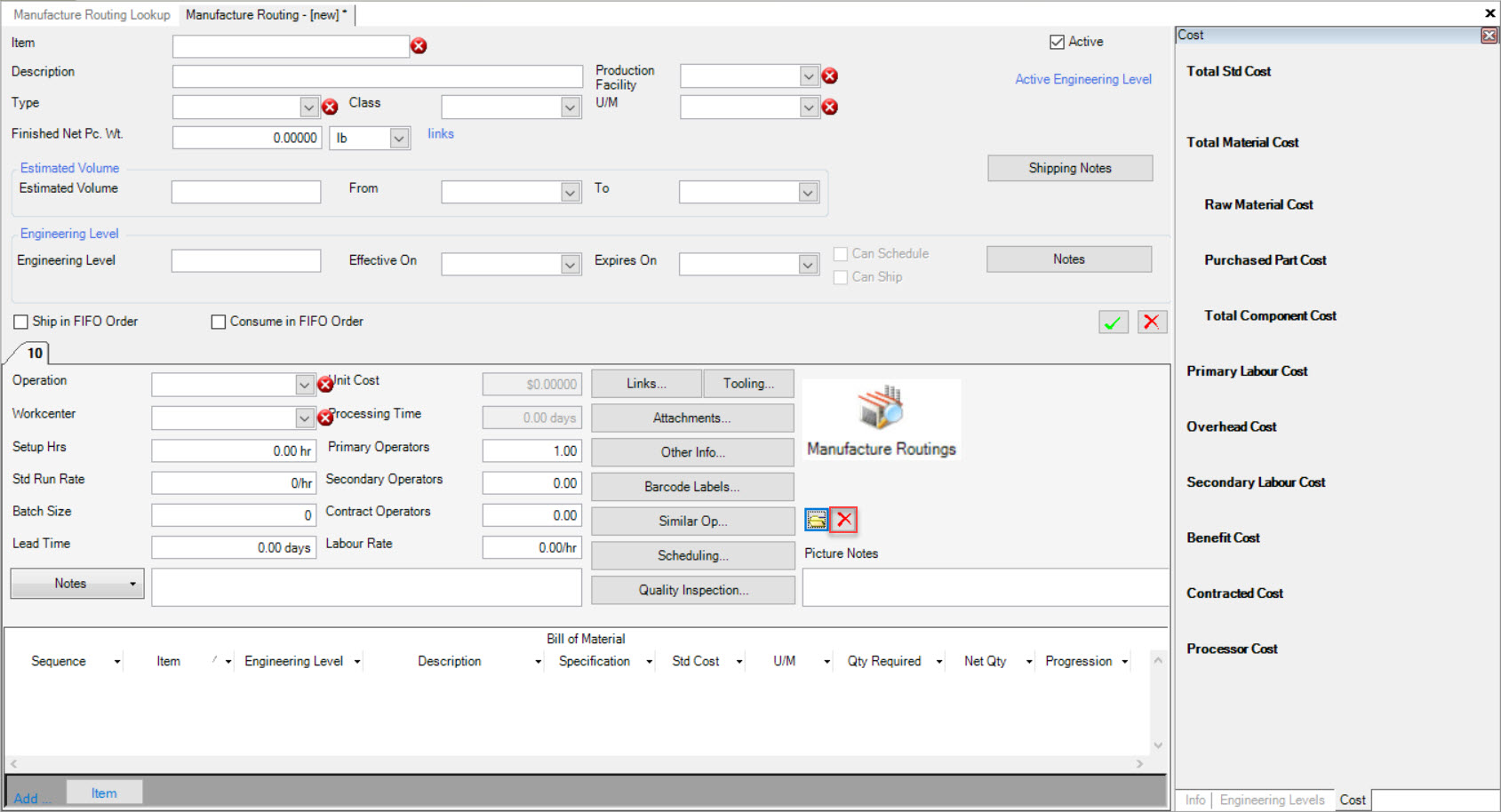
The picture that was attached to the Operation will now be deleted.
Make sure to save your changes before exiting the screen.
Adding Notes to an Operation Picture
Users can add Notes to a picture that they have added to the Operation. To do so, simply enter in the Notes in the available Picture Notes textbox below the picture on the Manufacture Routing screen.
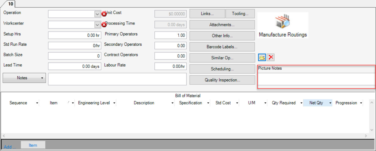
Once any necessary picture Notes have been added, make sure to save your changes before exiting the screen. The picture Notes will be visible to the Workcenter Operator.
Deleting Notes from an Operation Picture
To delete picture Notes, simply use your Backspace key in the available Picture Notes textbox. This will delete any unnecessary picture Notes.
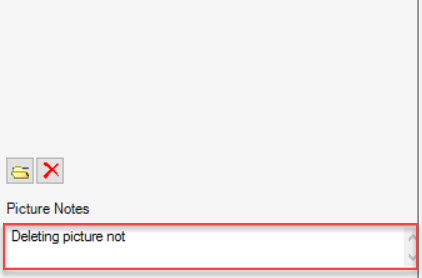
Make sure to save your changes before exiting the screen.
Note
If you wish to edit picture Notes instead of deleting them, simply use the Backspace key in the available Picture Notes textbox to edit any Notes.
Bill of Material
For each Operation process, the Bill of Material must be defined. The Bill of Material is also known as the material being used for an Operation.
In order to add an Item to the Bill of Material, it must first be defined in the system as a Purchased Item.
Once this has been done, the Item can then be added to the Bill of Material.
Note
For more information on Purchased Items, please see the Purchasing module.
Adding an Item to a Bill of Material
To add an Item to a Bill of Material, navigate to the bottom of the Manufacture Routing screen. Click on the  button. The Item Lookup
window will appear.
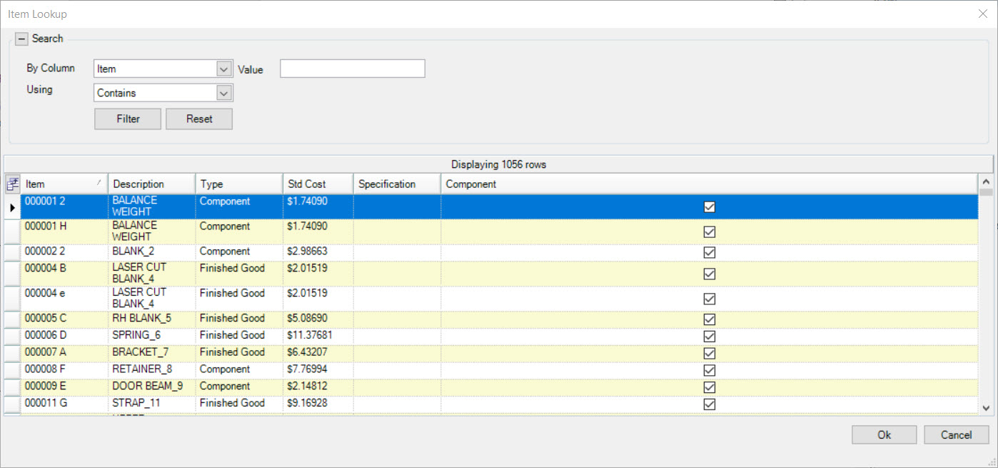
Locate the Item you wish to add to the Bill of Material and double-click on the Item row, or click on the  button.
A new row will appear on the Manufacture Routing screen, in the Bill of Material section located at the bottom of the screen. Now, users will be able to enter in additional information such as the Qty Required, Net Qty, and Progression. These fields are important when reducing the On-Hand balance of the Item added during Production.

Make sure to save your changes before exiting the screen.
Note
Users may add as many Items to the Bill of Material by repeating the above steps.
Deleting an Item from a Bill of Material
To delete an Item from a Bill of Material, simply highlight the appropriate row of the Item you wish to delete.
Use your Delete key and the highlighted Item will be deleted.
Make sure to save your changes before exiting the screen.
Adding a Picture to a Item
Users have the ability to add a picture to an Item on the Manufacture Routing screen.
To do so, make sure to click on the  tab located to the right of the screen.
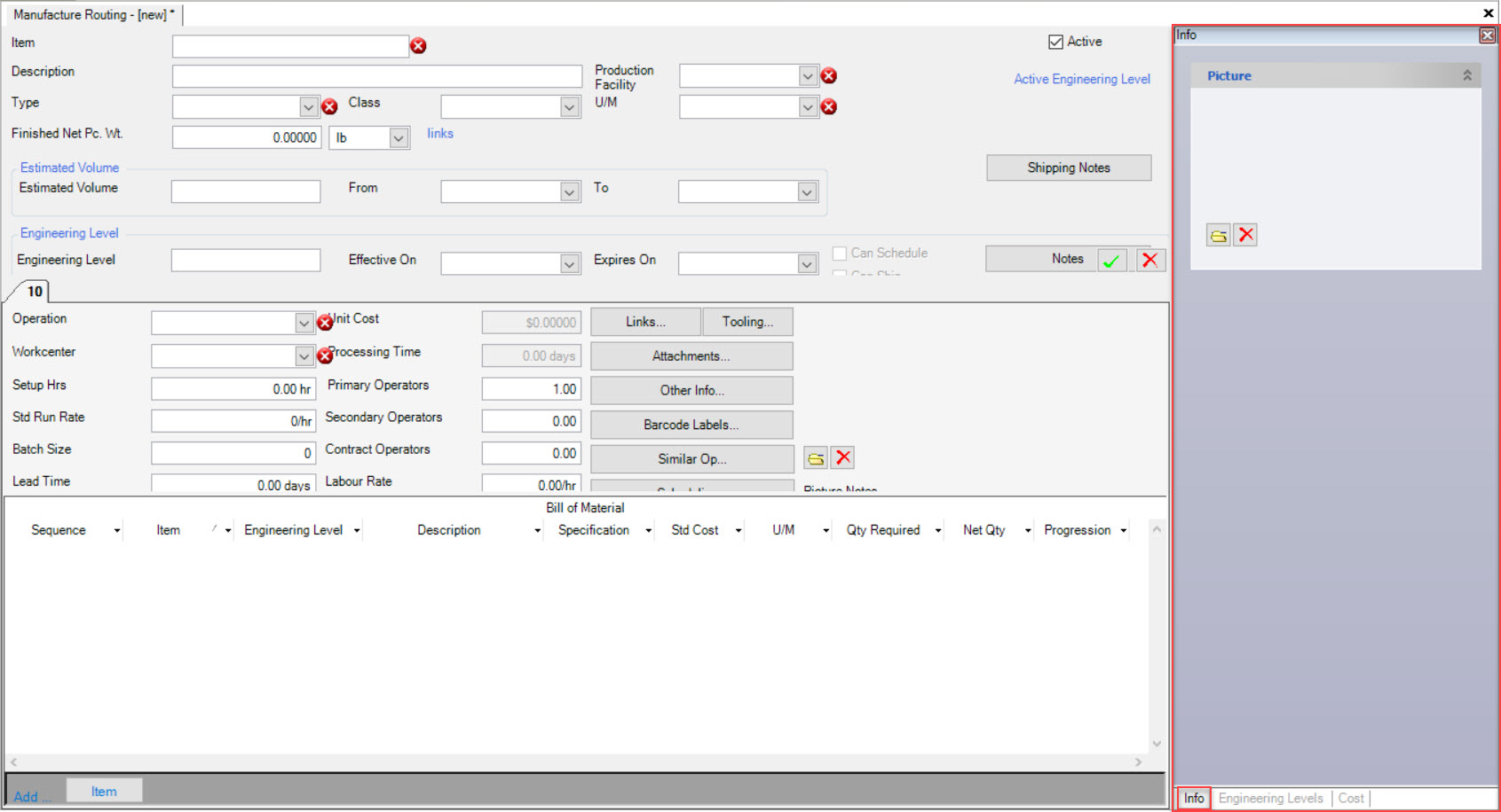
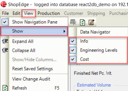
Note
If you are unable to view the  tab, select View > Show and make sure that it is selected.
Select the ![]() button. The system will then allow you to select a picture from your computer.
button. The system will then allow you to select a picture from your computer.
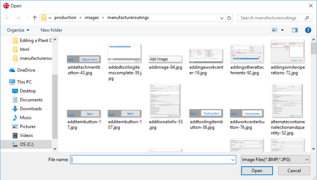
Once a picture has been selected, click on the  button.
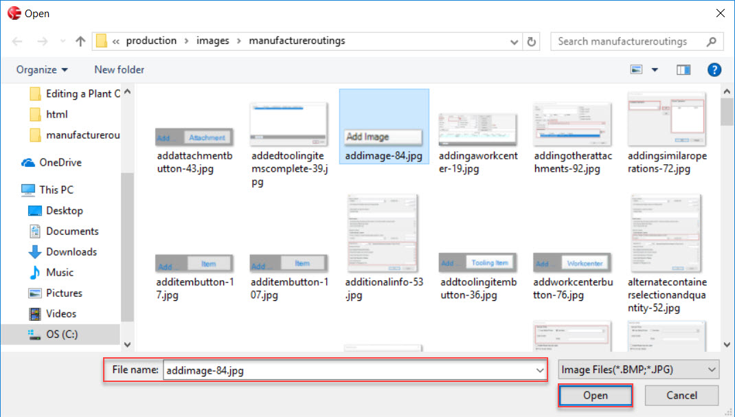
The picture will appear on the Manufacture Routing screen to the right. Make sure to save your changes before exiting the screen.
Note
The picture is added to only the Item on the Manufacture Routing screen; not the Operation therefore Operators will not be able to view this picture.
Deleting a Picture from an Item
To delete a picture from an item, make sure that the  tab is selected located to the right of the Manufacture Routing screen.
Click on the  button and the picture will be deleted.
Make sure to save your changes before exiting the screen.
Switching between Item Engineering Levels
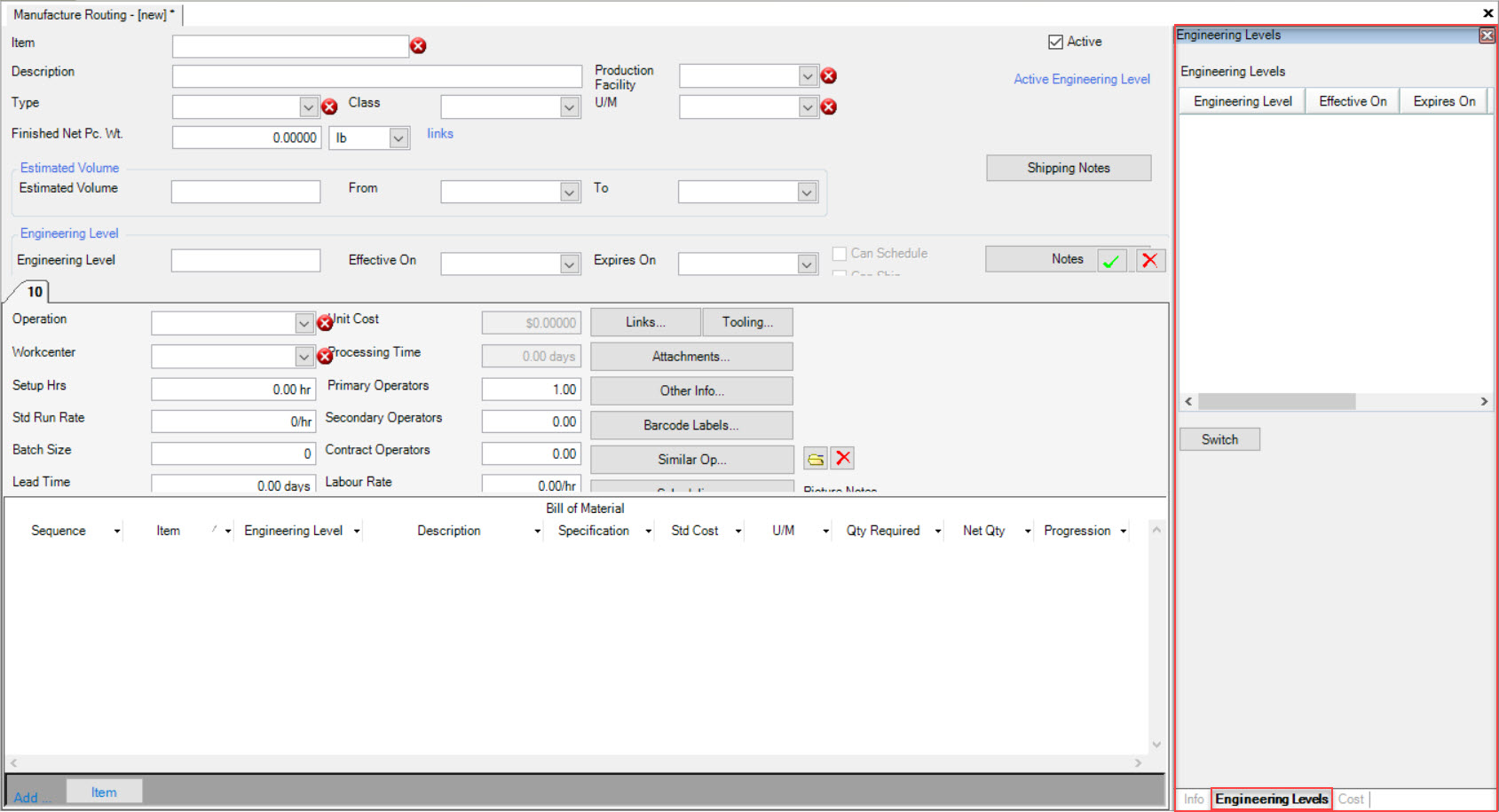
Users have the ability to switch between Item Engineering Levels on the Manufacture Routing screen.
To do so, make sure that the tab is selected located to the right of the screen.
Note
If you are unable to view the  tab, select View > Show and make sure that it is selected.

To switch between Item Engineering Levels, highlight the one you wish to switch to and click on the  button.
The Status of the old and new Engineering Levels will change between Pending and Current. The highlighted one will become the Current Engineering Level.
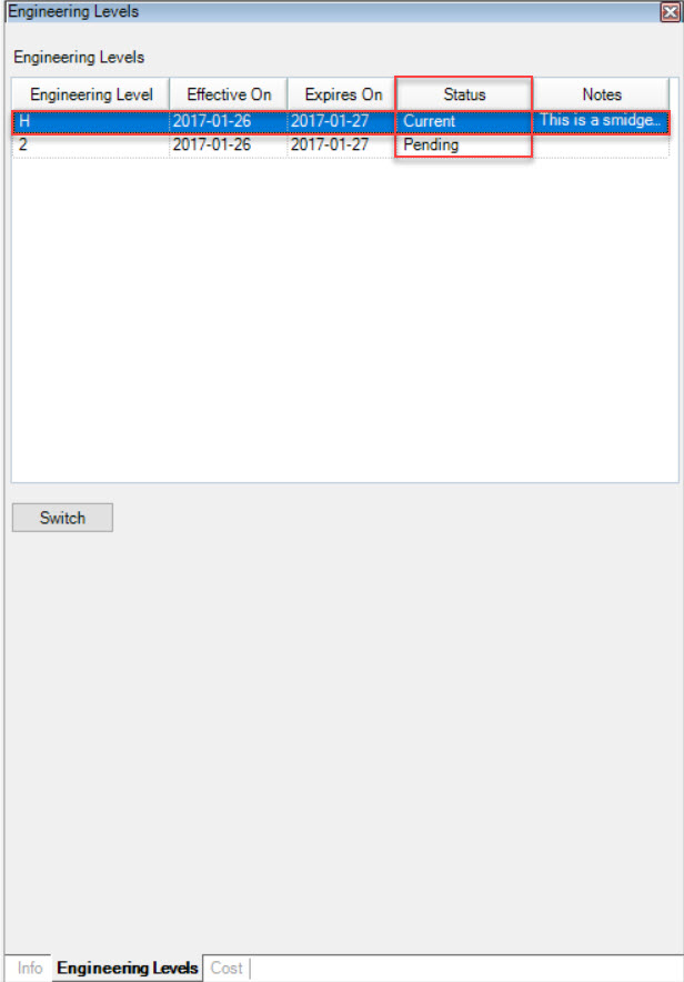
Make sure to save your changes before exiting the screen.
Viewing Item Cost Summary
Item Cost Summary is a quick summary of the costs of a particular Item. The Cost summary screen includes Total Std. Cost, Total Material Cost, Raw Material Cost, Purchased Part Cost, Total Component Cost, Primary Labour Cost, Overhead Cost, Secondary labour Cost, Benefit Cost, Contracted Cost, and Processor Cost. These costs are calculated from the Bill of Material for an Item (and Purchased Item costs), Item Pricing, and by various settings when navigating to Production > Admin. The ShopEdge system has a variety of Reports available for computing actual costs for an Item, as well as detailed costs.
To view the Item Cost Summary, make sure that the  tab located to the right of the Manufacture Routing screen.
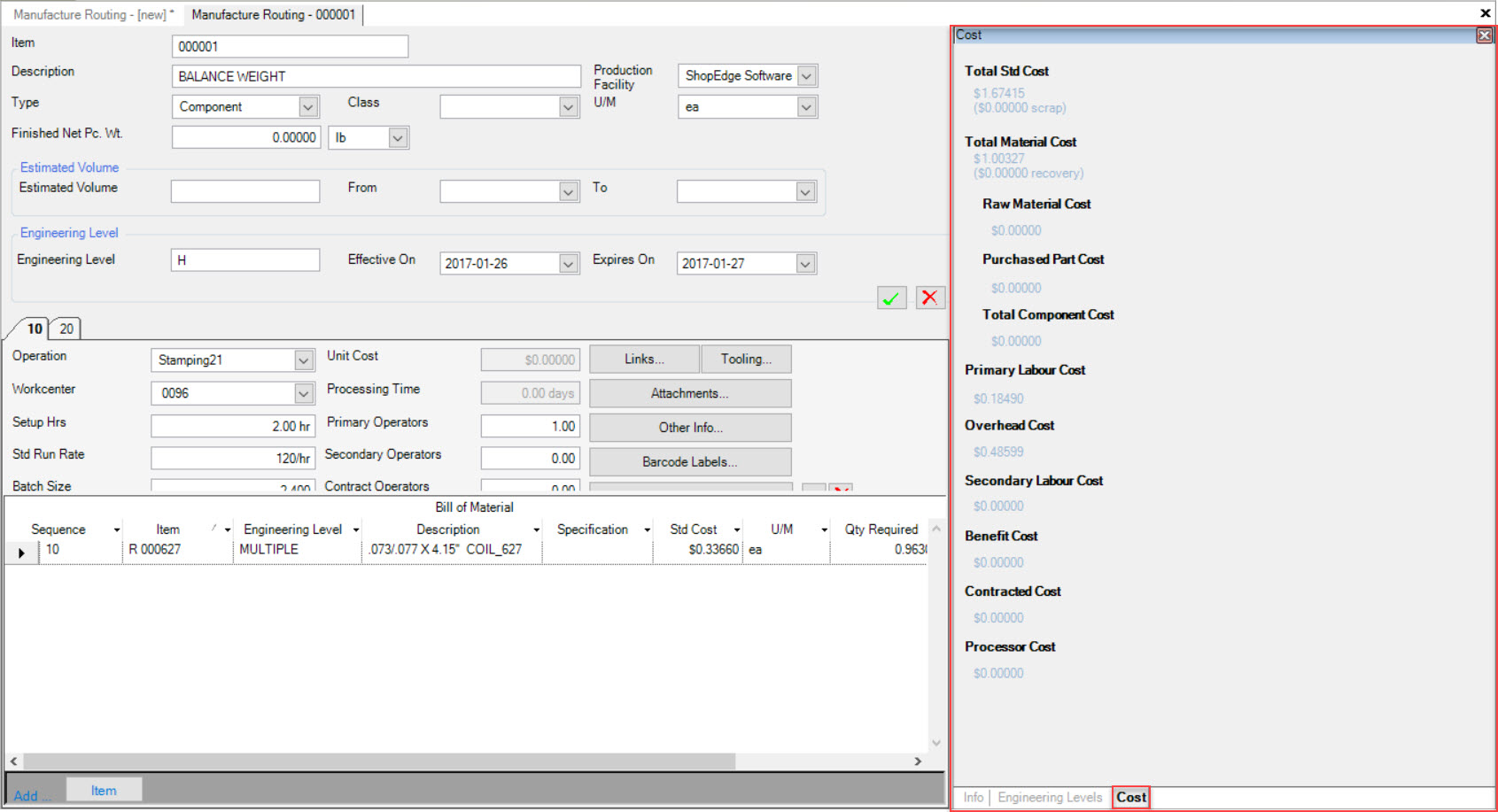
Note
If you are unable to view the  tab, select View > Show and make sure that it is selected.

Dock Audits
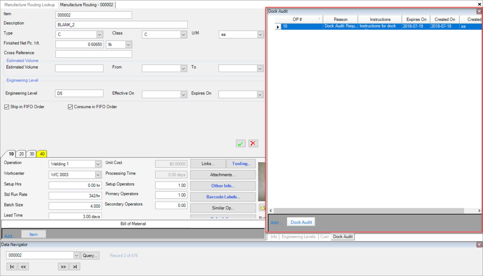
Users have the ability to add, edit, and make Dock Audits inactive from a Manufacture Routing in the system.
To view Dock Audits on a Manufacture Routing, make sure to select the  tab located to the right of the screen when the
Manufacture Routing is opened.
The active Dock Audits associated to that Manufacture Routing will be listed.
Note
There can only be one active Dock Audit per Manufacture Routing at a time.
Note
Please note that this functionality is for ShopEdge Version 2018.2.0.0 and newer.
Adding a Dock Audit
To add a Dock Audit to a Manufacture Routing, navigate to the  tab and click on the
 ![]() icon.
icon.
The Manufacture Routing Lookup screen will be displayed.

Locate the Manufacture Routing you wish to add a Dock Audit to and double-click on the appropriate row. The Manufacture Routing screen will be displayed with the details of the Item.

Make sure to select the  tab located to the right of the screen.
Then, click on the  button.
The Add Dock Audit window will appear where users must complete the necessary fields such as the OP #, Reason, Instructions, and the Expires On date. Then, click on the
 button.
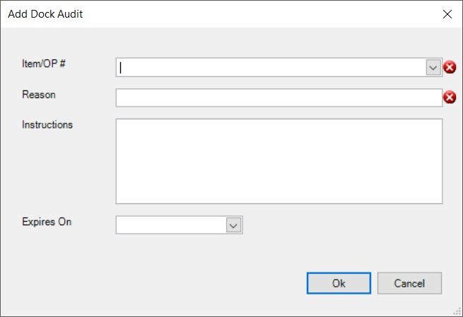
The Dock Audit will be added to the Manufacture Routing.
Make sure to save your changes before exiting the screen.
Note
Please note that this functionality is for ShopEdge Version 2018.2.0.0 and newer.
Editing a Dock Audit
To edit a Dock Audit on a Manufacture Routing, navigate to the  tab and click on the
 ![]() icon.
icon.
The Manufacture Routing Lookup screen will be displayed.

Locate the Manufacture Routing you wish to edit a Dock Audit for and double-click on the appropriate row. The Manufacture Routing screen will be displayed with the details of the Item.

Make sure to select the  tab located to the right of the screen.
Locate the Dock Audit you wish to edit and double-click on the appropriate row.
The Edit Dock Audit window will appear where users can make the necessary changes.
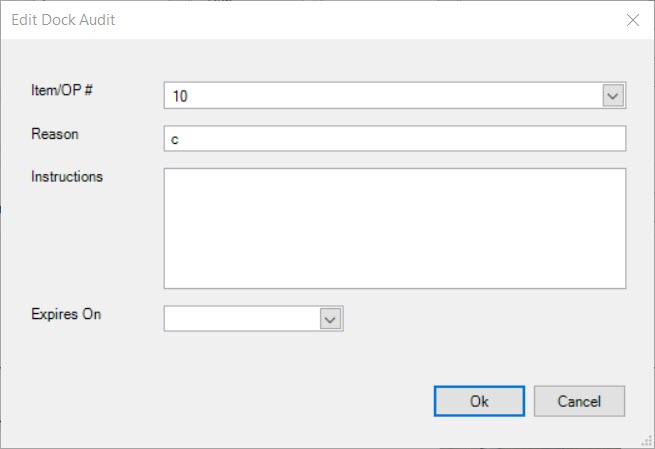
Once the necessary changes have been made, click on the  button.
Make sure to save your changes before exiting the screen.
Note
Please note that this functionality is for ShopEdge Version 2018.2.0.0 and newer.
Making a Dock Audit Inactive
To make a Dock Audit on a Manufacture Routing inactive, navigate to the  tab and click on the
 ![]() icon.
icon.
The Manufacture Routing Lookup screen will be displayed.

Locate the Manufacture Routing you wish to make a Dock Audit inactive for and double-click on the appropriate row. The Manufacture Routing screen will be displayed with the details of the Item.

Make sure to select the  tab located to the right of the screen.
There are two ways to make a Dock Audit inactive.
Locate the Dock Audit you wish to make inactive and highlight the appropriate row. Use your Delete key and when the system prompts you, select Yes.
The selected Dock Audit will be removed from the Manufacture Routing and be placed on the Dock Audit Management screen under the Inactive Dock Audits tab.
Make sure to save your changes before exiting the screen.
Note
Please note that this functionality is for ShopEdge Version 2018.2.0.0 and newer.
Importing and Exporting Manufacture Routings
Users have the ability to export a Manufacture Routing, including Operations, Bill of Material, and Quality inspections. You can select the detail to be exported. A file will be generated with the details. Once the file has been generated, it can be imported into another database to create a copy of the exported routing.
To export a Manufacture Routing, open the routing and navigate to File > Export to Xml....
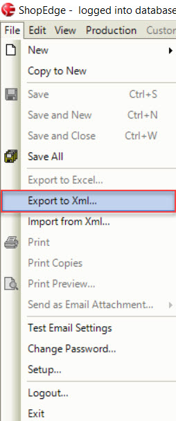
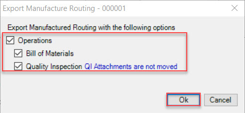
The Export Manufacture Routing window will appear. Select the appropriate checkboxes and click on the  button to export the data and save it.
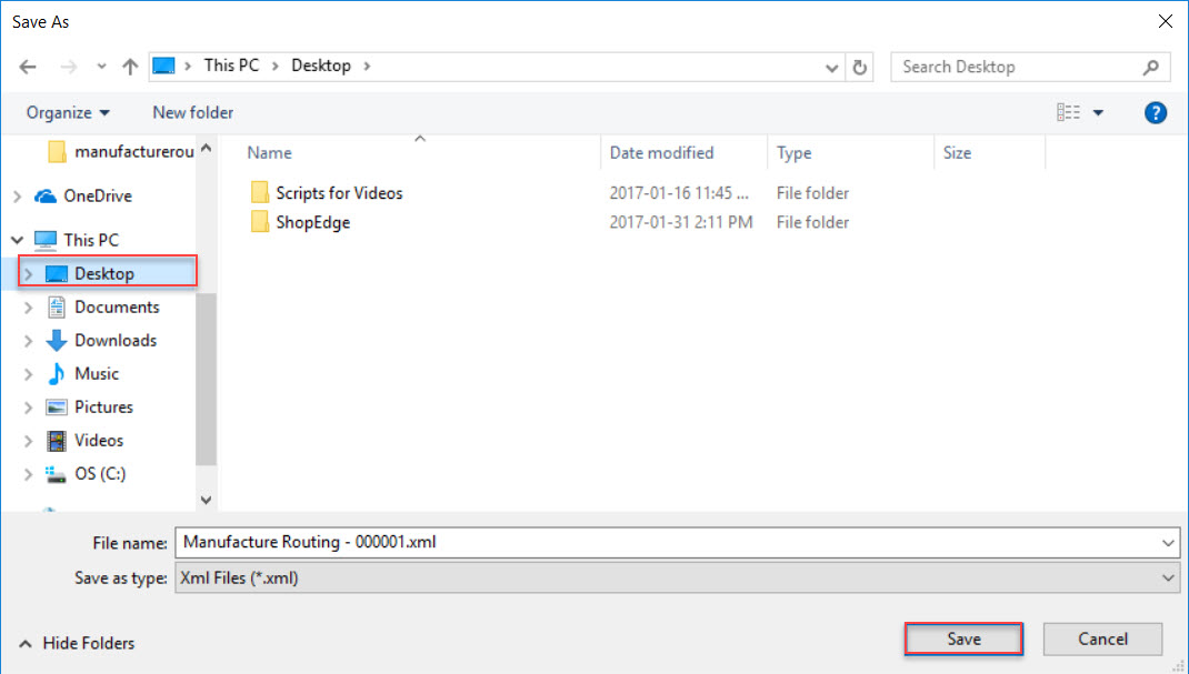
A window will appear where the system allows you to save the exported data to your computer. Select the location where you would like to save it and click on the  button.
To create new Manufacture Routing in another database from the exported data, first create a new routing using the File > New > Manufacture Routing option.
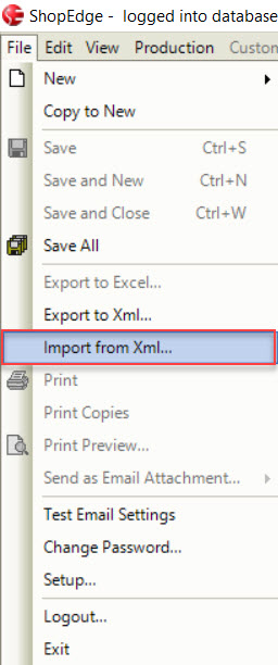
Then, navigate to File > Import from Xml....
A window will appear where you can select the import file from your computer. Once you have selected an import file, click on the  button.
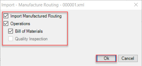
Then, select the detail you want imported from the Import Manufacture Routing window. You do not need to import all of the data from the export file. Some options may be disabled based on the
information contained in the export file. Click on the  button when you are finished.
The data will be populated to the new Manufacture Routing from the export file. You can edit as needed.
Make sure to save your changes before exiting the screen.
Editing Manufacture Routings
Users have the ability to edit a Manufacture Routing. For each field/option that users may edit, please see Adding a New Manufacture Routing for more detailed information.
Once all changes have been made to a Manufacture Routing, make sure to save your changes before exiting the screen.
